
Basic Documentation
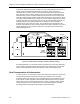

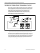
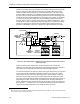
Table Of Contents
- About this Application Guide
- Chapter 1–Introduction
- Chapter 2–Goals of the Laboratory Environment
- Chapter 3–Unique Ventilation Needs of a Laboratory Facility
- Chapter 4–Ventilation Systems Classification
- Chapter 5–Laboratory Facility Exhaust Systems
- Chapter 6–Laboratory Containment Units - Ventilation
- Chapter 7–Room Ventilation, Makeup Air, and Pressurization Control Systems
- Chapter 8–Laboratory Temperature and Humidity Control Systems
- Chapter 9–Laboratory Emergencies - Ventilation System Response
- Chapter 10–Laboratory Ventilation System - Validation
- Chapter 11–Laboratory Ventilation System - Commissioning
- Glossary
- Index

Chapter 8–Laboratory Temperature
and Humidity Control Systems
Chapter 8 discusses laboratory room control systems that maximize worker
concentration and productivity. It includes the following topics:
• Room temperature control by temperature sensing
• Variable air volume room temperature control
• Room temperature control by BTU compensation
Like most work areas, a comfortable laboratory room environment helps maximize
worker concentration and productivity. A comfortable laboratory room environment
also removes the inducement for occupants to add portable fans, heaters or use
makeshift methods in an attempt to rectify uncomfortable conditions. Such actions
can hinder the ability of the ventilation system to maintain a safe environment.
Therefore, a laboratory ventilation system must be precisely controlled to ensure it
can provide an ambient environment that will meet both varying personal preferences
and process requirements.
Room Temperature Control by Temperature
Sensing
Figure 15 shows a laboratory ventilation system with the essential control equipment
to provide proper room ventilation and pressurization as well as some additional
elements to achieve basic room temperature control. The simple arrangement of
Figure 15 is applicable to virtually all laboratory rooms served by constant air volume
HVAC systems, and under certain conditions can be applied to laboratory rooms
served by variable air volume HVAC systems.
Figure 15 also shows the utilization of a reheat coil in the air supply terminal that
provides air for the laboratory room. The room controller provides a control signal to
the reheat coil valve to modulate the amount of hot water flowing through it and
establishes the temperature of the room supply air. The control signal to the reheat
coil valve is varied by the room controller in response to the room temperature as
indicated by the room temperature sensor. This temperature control arrangement
ensures that the supply air temperature will in turn maintain the desired room
temperature.
Siemens Building Technologies, Inc. 73