
Basic Documentation
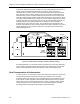

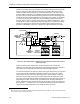
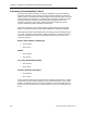
Table Of Contents
- About this Application Guide
- Chapter 1–Introduction
- Chapter 2–Goals of the Laboratory Environment
- Chapter 3–Unique Ventilation Needs of a Laboratory Facility
- Chapter 4–Ventilation Systems Classification
- Chapter 5–Laboratory Facility Exhaust Systems
- Chapter 6–Laboratory Containment Units - Ventilation
- Chapter 7–Room Ventilation, Makeup Air, and Pressurization Control Systems
- Chapter 8–Laboratory Temperature and Humidity Control Systems
- Chapter 9–Laboratory Emergencies - Ventilation System Response
- Chapter 10–Laboratory Ventilation System - Validation
- Chapter 11–Laboratory Ventilation System - Commissioning
- Glossary
- Index

Chapter 8–Laboratory Temperature and Humidity Control Systems
Note that in the laboratory room example just reviewed, raising the fume hood sash
does not change the total heat gain of the room. The room’s heat gain remains
virtually constant and is mainly due to outside wall temperature, sun rays coming
through windows (if present), room lighting and other heat producing equipment in
the room. Thus, the room heat load in BTUs gained per hour does not change even
though the amount of airflow (total exhaust and supply) does change. Consequently,
it is necessary to keep the cooling effect of the incoming air (BTUs removed per
hour) the same in order to avoid a change in the room ambient temperature. This is
essentially what a BTU compensation control strategy does. It keeps the incoming
supply air’s cooling effect constant even though the supply airflow increases or
decreases substantially. In this way, a swing in the room temperature is avoided.
CFM
SUPPLY
TERMINAL
ROOM
CONTROLLER
VARIABLE
VOLUME
FUME HOODS
EXHAUST
ROOM
GENERAL
EXHAUST
CFM
CFM
CFM
TEMP
ROOM
TEMPERATURE
SENSOR
REHEAT COIL
3 - WAY VALVE
SUPPLY AIR
TEMPERATURE
SENSOR
Figure 16. BTU Compensation Temperature Control System for Small VAV Chemical
Laboratory Room.
Figure 16 shows a BTU compensation control arrangement for a small VAV
laboratory room. Because of the potential for rapid changes in laboratory airflows in
such rooms, BTU compensation temperature control should be applied.
The control arrangement in Figure 16, differs from Figure 15 by having a 3-way valve
at the reheat coil and a discharge temperature sensor in the supply air. A 3-way
valve prevents the hot water in the pipe leading to the reheat coil from cooling off.
When the valve is totally closed, the hot water continuously circulates right at the
valve thus ensuring the water is always hot and ready for use even when there is no
flow through the valve and reheat coil. The addition of the discharge temperature
sensor enables the room controller to calculate the cooling effect of the supply air in
BTUs per hour.
26
In addition, the room controller will use this temperature sensor to
control the discharge temperature of the supply air when necessary.
26
When the room is at the desired temperature and the supply airflow has been stable, the room controller calculates the
room’s heat load by the following relationship:
76 Siemens Building Technologies, Inc.