
Basic Documentation
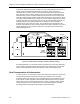

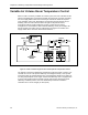
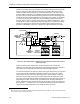
Table Of Contents
- About this Application Guide
- Chapter 1–Introduction
- Chapter 2–Goals of the Laboratory Environment
- Chapter 3–Unique Ventilation Needs of a Laboratory Facility
- Chapter 4–Ventilation Systems Classification
- Chapter 5–Laboratory Facility Exhaust Systems
- Chapter 6–Laboratory Containment Units - Ventilation
- Chapter 7–Room Ventilation, Makeup Air, and Pressurization Control Systems
- Chapter 8–Laboratory Temperature and Humidity Control Systems
- Chapter 9–Laboratory Emergencies - Ventilation System Response
- Chapter 10–Laboratory Ventilation System - Validation
- Chapter 11–Laboratory Ventilation System - Commissioning
- Glossary
- Index

Room Temperature Control by BTU Compensation
To describe the way a BTU compensation control scenario limits room temperature
swings from occurring, we’ll again refer to the previous laboratory room. Assume that
the ventilation system arrangement is the same, except that a supply air temperature
sensor and a 3-way valve are used. With these two changes and the inclusion of the
appropriate BTU compensation control program in the room controller, the BTU
compensation room temperature control strategy can be applied. Consider again the
conditions whereby it is a warm summer day and the fume hood sash is initially
closed. The total room exhaust is 450 cfm and the room supply is 200 cfm. As
before, the incoming supply air would be near its minimum temperature of about
54°F. Again, due to the low supply airflow rate the room is free of objectionable cold
drafts.
Consider again someone raising the sash of the six-foot fume hood until it is fully
open. First, the fume hood controller quickly increases the fume hood exhaust to
1,250 cfm to maintain the proper fume hood average face velocity. Next, the room
controller must quickly increase the supply airflow to 1,000 cfm to provide makeup air
for the increased fume hood exhaust. (As before, the difference between the room
supply and total exhaust airflow is maintained at 250 cfm to ensure the room at a
negative static pressure.)
However, as soon as a significant change in supply airflow is required, the room
controller’s BTU Compensation control strategy is activated. The first action is to
calculate the proper supply air discharge temperature required to maintain the same
cooling effect (BTU per hour removal rate) at the higher supply airflow. Then the
controller modulates the reheat coil valve to achieve this new required supply air
discharge temperature. In the forgoing example, the supply airflow must increase
from 200 cfm to 1,000 cfm or be five times as much. However, at 200 cfm the supply
air requires a 54°F temperature to maintain the required cooling effect to offset the
room’s heat load of 4,400 BTUs per hour.
27
However with 1,000 cfm (five times more
supply airflow) the same room heat load will be offset with only one-fifth of the
previous 20°F supply air temperature rise. Thus, the new supply air temperature
need only be about 70°F
28
. With this new supply air discharge temperature, the
balance is maintained between the room’s heat gain and the supply air’s cooling
effect. Consequently the laboratory temperature remains constant and the new
supply air temperature of 70°F is not perceived by the occupants as a cold draft as
was the previous 54°F supply air temperature.
If the fume hood sash is suddenly closed after having been open for a time, the room
controller can quickly readjust (lower) the incoming supply air temperature to again
quickly meet the room’s need and avoid a room temperature rise. Note that the BTU
Compensation control action is engaged whenever a substantial change occurs in
the room’s airflow. Under stable room airflow conditions, temperature control is
based primarily upon the input signal of the room temperature sensor.
Heat Load = Temperature Rise × Supply Airflow cfm × 1.10
Temperature rise is the difference between the supply and room air temperatures. Supply Airflow cfm is the supply
airflow when the room is at the proper ambient temperature. 1.10 is a thermodynamic constant and is in units of BTUs
per hour per °F per cfm. The product of these three factors then expresses the room heat gain in BTUs per hour.
27
As explained in the previous footnote, the heat load is calculated as Temperature Rise × Supply Airflow cfm × 1.10. In
this example the Temperature Rise is 74°F to 54°F or 20°F. Therefore, the Heat Load is 20°F × 200 cfm × 1.10 or
4,400 BTUs/hr.
28
Using the new supply values yields 4°F × 1000 cfm × 1.10 again equates to the room’s heat load of 4,400 BTUs/hr.
Therefore, the cooling effect remains unchanged.
Siemens Building Technologies, Inc. 77