
Basic Documentation
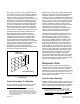
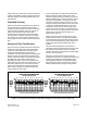
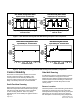
Table Of Contents

Siemens Industry, Inc. Page 3 of 8
Document No. 149-975
accurately sense and measure the controlled
variable
(room temperature in this example) is a
fundamental requirement for any control process.
Response Time
Let's consider the effect of a room temperature
sensor that is very accurate, but unfortunately has a
slow response time. This results in slow control
response and in the case of room temperature, it
would probably result in room temperature swings.
The room becomes too warm and then gets too cool
as the sensor's response lags too far behind actual
room conditions. Thus, the faster the response time,
the less likely the control process will experience
overshoot and undershoot.
Control Stability
Consider what is often times the most prevalent
reason for poor control—lack of stability. If
something in a room interferes with the room
temperature sensor's ability to consistently sense
actual room temperature, control stability will likely
be affected. If a light bulb or other source of heat
were located near the sensor, the resulting
intermittent heat would likely cause the temperature
sensor to erroneously respond as though room
temperature was suddenly higher whenever the heat
source was present. Also, if the sensor were on an
outside wall or subject to outside air infiltration, it
would very likely indicate erroneous room
temperatures. Thus, external factors can have an
adverse effect on what might otherwise be a simple
and straightforward control process by interfering
with the sensor's ability to accurately indicate actual
conditions.
Control Accuracy
Sash Position Sensing
As stated, sash position sensing based control takes
a mathematical approach to maintain the required
average fume hood face velocity. With sash position
sensing the controller can determine the total open
area of the fume hood, and thus calculate exactly
how much exhaust airflow is required to maintain the
required average face velocity of the incoming
makeup air through the sash opening.
Sash position sensing can use various types of
sensors to determine actual sash position within a
small fraction of an inch. The maximum resulting
error in determining the total fume hood open area
then depends upon the size of the sash opening. For
instance, if a typical vertical rising sash was fully
open at a height of about 28 inches and the sash
sensor was accurate to within ¼ of an inch, the open
sash area could be accurately determined to within
1% (0.25 inches divided by 28 inches). If the sash
opening were 18 inches, the potential error would
still be only a little more than 1%. And, at a sash
opening of 12 inches, the error would still only be
about 2%.
However, you must also consider the measurement
accuracy of the fume hood exhaust airflow since this
is also a key component of the sash position based
sensing control arrangement, as shown in Figure 1.
Note that airfl
ow measurement accuracy is mainly a
factor of airflow velocity—the higher the airflow
velocity, the greater the potential measurement
accuracy.
Fume hood exhaust airflow in the exhaust duct
typically ranges between a minimum of 500 fpm and
up to 3000 fpm. At these airflow rates the velocity
pressure corresponds to 0.015 and 0.560 inches of
water respectively. These relatively robust signals
enables certified airflow measurement accuracies of
at least ±5% at the low velocity (500 fpm) to more
typically ±2% or ±3 % at higher velocities
2
.
Therefore, considering the net effect of both the 1%
or 2% accuracy in the open sash area determination
and the 2% to 3% typical exhaust airflow
measurement accuracy, the overall average face
velocity control accuracy can be expected (and has
been demonstrated) to be within ±5% for sash
position sensing based control.
Side Wall Sensing
A side wall airflow measurement sensor typically
consists of a differential pressure type of sensor
because some sources believe that differential
pressure measurement gives the best
representation of the fume hood's incoming average
airflow velocity. However, the attainable airflow
velocity measurement accuracy that can be obtained
by differential pressure measurement at extremely
low airflows is questionable. Note that with reference
to the Bernoulli equation for airflow
3
, the differential
pressure corresponding to the typically desirable
2. With side wall sensing the airflow velocity is normally the
desired face velocity—around 100 fpm. In terms of air
velocity this is very low and extremely difficult to accurately
measure.
3. Airflow Velocity fpm = 4005 √ dP