
Basic Documentation
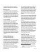
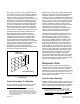
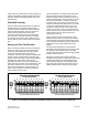
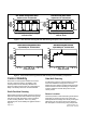
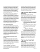
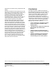
Table Of Contents

050
100 150 200 250 300
Side Wall Sensing Based Control
Response Time Tests: 4 Foot Fume Hood
ELAPSED TIME - SECONDS
650 CFM
180 CFM
FUME
HOOD
EXHAUST
AIRFLOW
CFM
200
300
400
500
600
700
800
100
050
100 150 200 250 300
Side Wall Sensing Based Control
Response Time Tests: 4 Foot Fume Hood
ELAPSED TIME - SECONDS
650 CFM
180 CFM
FUME
HOOD
EXHAUST
AIRFLOW
CFM
200
300
400
500
600
700
800
100
200
300
400
500
600
700
800
100
0 50 100 150 200 250 300
Sash Position Sensing Based Control
Response Time Tests: 4 Foot Fume Hood
FUME
HOOD
EXHAUST
AIRFLOW
CFM
ELAPSED TIME - SECONDS
200
300
400
500
600
700
800
100
650 CFM
180 CFM
0 50 100 150 200 250 300
Sash Position Sensing Based Control
Response Time Tests: 4 Foot Fume Hood
FUME
HOOD
EXHAUST
AIRFLOW
CFM
ELAPSED TIME - SECONDS
200
300
400
500
600
700
800
100
200
300
400
500
600
700
800
100
650 CFM
180 CFM
Figure 4. Sash Position Sensing and Side Wall Sensing–Response Time Comparison.
050
100 150 200 250 300
Sash Position Sensing Based Control
System Stability Test: 4 Foot Fume Hood
ELAPSED TIME - SECONDS
FUME
HOOD
EXHAUST
AIRFLOW
CFM
200
300
400
500
600
700
800
100
900
1000
050
100 150 200 250 300
Sash Position Sensing Based Control
System Stability Test: 4 Foot Fume Hood
ELAPSED TIME - SECONDS
FUME
HOOD
EXHAUST
AIRFLOW
CFM
200
300
400
500
600
700
800
100
200
300
400
500
600
700
800
100
900
1000
050
100 150 200 250 300
Side Wall Sensing Based Control
System Stability Test: 4 Foot Fume Hood
ELAPSED TIME - SECONDS
FUME
HOOD
EXHAUST
AIRFLOW
CFM
200
300
400
500
600
700
800
100
900
1000
050
100 150 200 250 300
Side Wall Sensing Based Control
System Stability Test: 4 Foot Fume Hood
ELAPSED TIME - SECONDS
FUME
HOOD
EXHAUST
AIRFLOW
CFM
200
300
400
500
600
700
800
100
200
300
400
500
600
700
800
100
900
1000
Figure 5. Sash Position Sensing and Side Wall Sensing–Control Stability Comparison.
Control Stability
Even when a control system includes an accurate
and very responsive sensor, the stability of the
control process can be adversely affected if the
sensor is subject to factors that can compromise its
ability to accurately sense the controlled variable.
Sash Position Sensing
Sash position sensing is virtually immune to the local
airflow and temperature induced factors that typically
exist at fume hoods and have a pronounced effect
on other sensing methods. This is very clearly
indicated by the control stability test graphs shown in
Figure 5.
Side Wall Sensing
As indicated in Figure 5, side wall sensing control is
much less stable due in large part to the room
airflows and other ambient conditions that frequently
exist around fume hoods. Following is a discussion
of these conditions and their likely effect on face
velocity control.
Sensor Location
The basic premise of side wall sensing is that airflow
measured at a single point in a fume hood's side
wall represents the average face velocity at the open
sash area in the front of the fume hood. However
this assumption is not shared by many independent
Page 6 of 8 Siemens Industry, Inc.
Document No. 149-975