
Operating Instructions


Laboratory Room Controller Owner's Manual
1-2 Siemens Building Technologies, Inc.
LRC Configurations
The LRC is equipped to handle a variety of combinations of ventilation devices in one room.
Each LRC in your system is initially set up to cover the equipment installed at that time.
Laboratory ventilation systems are known to change from time to time, usually as exhaust
devices are added, or removed. This section explains various ways your LRC may be
adapted to accommodate changes in the ventilation equipment. Contact your local Siemens
Building Technologies, Inc. representative for more specific information about your options.
Two versions of the LRC are available, one for pneumatic actuation (Applications 2601, 2602,
and 2603) and the other for electronic actuation (Applications 2611, 2612, and 2613).
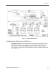
Configurations with General Exhaust
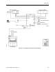
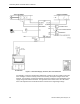
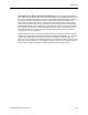
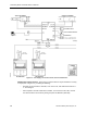
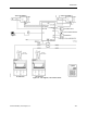
One Supply, One Hood, One General Exhaust - This is the most basic arrangement. The
supply flow and general exhaust are controlled as described in
Chapter 3, Controlling
Laboratory AirFlow
, to provide the required quantity of supply and exhaust air to meet both
the needed ventilation and temperature for the laboratory space. The supply may be a single
or dual duct terminal. If it is a single duct terminal, the controller runs Application 2601 or
2611 (refer to Figure 1-1); if it is dual duct terminal, the controller runs Application 2603 or
2613 (refer to Figure 1-2).