
Operating Instructions

Introduction
Siemens Building Technologies, Inc. 1-5
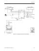
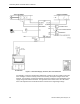
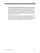
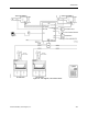
One Supply, Two or More Hoods, One General Exhaust - This configuration operates the
same way as the One Supply, One Hood, One General Exhaust. The supply flow and general
exhaust are controlled as described in
Chapter 3, Controlling Laboratory AirFlow
, to provide
the required quantity of supply and exhaust air to meet both the needed ventilation and
temperature for the laboratory space. The difference is that instead of just one fume hood,
there can be a maximum of four. If more than one fume hood is present, a Fume Hood Flow
Module (FFM) must be used. A FFM receives airflow signals from up to four FHCs, combines
those signals, and delivers one combined airflow signal to the LRC. The FFM detects open
circuit inputs so that it can correctly average only the signals connected to it, even when a
FHC signal fails. Refer to Figure 1-3.
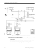
Adding more fume hoods to a system that only has one fume hood means adding a FFM to
combine the signals. Adding fume hoods with Siemens Building Technologies, Inc. controls to
a system that already has a FFM does not require any new room control components. In
either case, it is necessary to re-evaluate the limits on the supply and exhaust airflows. These
limits may need to be adjusted, or new supply or exhaust may need to be added. It may also
be necessary to adjust the scaling factor that interprets the fume hood flow signal.