
Operating Instructions

Siemens Building Technologies, Inc. 2-1
2
Hardware
Laboratory Room Controller
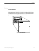
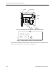
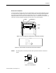
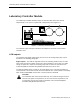
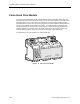
The Laboratory Room Controller (LRC), Figure 2-1, controls airflow and temperature for
laboratories with VAV or constant volume two position fume hoods.
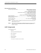
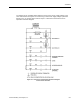
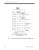
The LRC has the following inputs and outputs:
IN Pneumatic Actuation Electronic Actuation
2 air velocity 0 - 2 in wc 0 - 2 in wc
1 room temperature sensor Thermistor Thermistor
1 hood flow signal 0 - 10 Vdc 0 - 10 Vdc
Occupancy dry contact dry contact
Alarm dry contact dry contact
OUT
2 flow damper actuators 0 - 15 psi Floating control high speed
actuator
1 reheat (or mixing) actuator 0 - 15 psi 0 - 10 Vdc
1 local alarm 24 Vac 24 Vac
1 occupancy indicator 24 Vac 24 Vac