
Operating Instructions

Hardware
Siemens Building Technologies, Inc. 2-5
Electronic Actuation
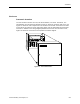
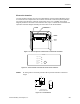
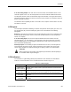
The LRC enclosure houses the LCM, one terminal block, and two Autozero Modules. Figure
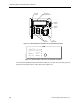
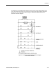
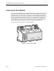
2-4 shows the LRC components in the enclosure. Pneumatic connections (for flow pickups)
are made on the side of the enclosure via four ports (
Figure 2-5
). In addition to the wiring
diagram provided on the inside of the enclosure cover,
Figure 2-9
shows the connections and
equivalent schematic diagram including the connections to the AO-E modules.
-
+s
FUM0323R1
AUTOZERO
MODULE
LABORATORY
CONTROLLER MODULE
TERMINAL
BLOCK
AUTOZERO
MODULE
Figure 2-4. LRC Components and Enclosure for Electronic Actuation.
Supply 1 air flow Hi
Exh or Supply 2
air flow Lo
Exh or Supply 2
air flow Hi
Supply 1 air flow Lo
LAB0176R1
Figure 2-5. LRC Pneumatic Connections for Electronic Actuation.
NOTE:
An earth ground is necessary with the LRC to provide resistance to electrical
surges.
LAB0108R1
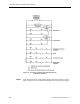
1 - 1/4
(32)
15/16
(24)
1 - 3/8
(34)
DIMENSIONS IN INCHES
MILLIMETERS IN PARENTHESES
Figure 2-6. Terminal Block.