
Operating Instructions
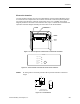

Laboratory Room Controller Owner's Manual
2-6 Siemens Building Technologies, Inc.
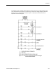
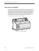
Laboratory Controller Module
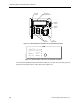
The Laboratory Controller Module (LCM) is an electronic DDC device that controls
independently, or as a part of a system with a field panel (refer to Figure 2-7).
LAB0143R1
1234567 9
10
11 12 13 14 15 16 17 18 19 20 21 22 23 24
C
EGND
BST
LED 1
RX
LED 2
TX
LED 3
LED 4
LED 5
LED 6
LED 7
LED 8
LED 9
LED 10
LED 11
H
8
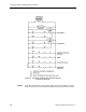
Figure 2-7. Laboratory Controller Module.
The controller output and input terminations are labeled on the inside of the controller
enclosure cover.
LCM outputs
The LCM has eight digital outputs (DOs) and one 0–10 Vdc analog output (AO). Each is
described in the following paragraphs.
Digital outputs - The LCM has eight DOs that are AC switching TRIACS. They are solid-
state contact closures that switch 24 Vac only, with a maximum of 12 VA each. If a higher
voltage or higher VA is required, interposing relays that are similar or equivalent to the
Terminal Equipment Controller Relay Module (P/N 540-147) must be used.
The DOs are labeled “DO1” to “DO8” on the LCM's plastic cover. The DOs correspond to
screw terminals 1 to 16. Each DO has two screw terminals. One screw terminal is a Normally
Open terminal, labeled NO, and the other is 24 Vac Common, labeledC.
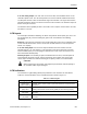
CAUTION:
The controller’s DOs control 24 Vac loads only. The maximum rating is 12 VA for
each DO. For higher VA requirements, or for 110 or 220 Vac requirements, use
an interposing 24 Vac relay similar or equivalent to the Terminal Equipment
Controller Relay Module (P/N 540-147).