
Operating Instructions

Hardware
Siemens Building Technologies, Inc. 2-9
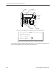
0–10 Vdc analog output—The LRC has one 0–10 Vdc AO, and it is labeled “AO1” on the
controller’s plastic cover. The AO corresponds to the screw terminals numbered 23 and 24.
The AO point consists of two screw terminals: signal and common. The signal and common
terminals supply the output to the device connected to the controller. The maximum output of
AO1isfactorysetto10Vdc.
The maximum drive capability of AO1 is 10 mA DC. This is equal to a load of 500 Ω at 5 Vdc,
and 1000 Ω at 10 Vdc.
LCM inputs
The LCM inputs include the following: one Room Temperature Sensor (RTS) port, one 0–10
Vdc analog input (AI), and two auxiliary (DI) ports. Each is described in the following
paragraphs.
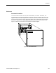
RTS port—The RTS port is located on the far right-hand side of the LCM. It is labeled “RTS”
on the controller board and is used to connect the controller board to a room temperature
sensor or to a laptop.
0–10 Vdc analog input—The 0–10 Vdc input is labeled “AI3” and is located at screw
terminals signal (+) 17 and common (-) 18. This input is used for the flow from one Fume
Hood Controller (FHC) or for averaging the flow from two to four FHCs connected to a 4:1
Fume Hood Flow Module (FFM).
Auxiliary DI ports—The auxiliary DI ports are labeled “DI2” and “DI4,” and correspond to
screw terminals 19 and 20, and 21 and 22, respectively. These inputs only accept a dry
contact input. Possible uses include attaching an occupancy switch, or an alarm switch.
CAUTION:
When connecting to the positive and negative input terminals, maintain polarity or
the controller board may be damaged.
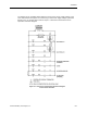
LCM indicators
The LCM has 11 Light Emitting Diode (LED) indicators. Their functions are described in
Table 2-1, and their locations on the controller board are shown in Figure 2-7.
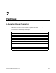
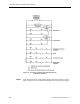
Table 2-1. Indicator Lights
LED Type (label) Description
Digital output
(LED 4 to LED 11)
ON/OFF status of DO1 to DO8. Lighted LED indicates its associated DO is
energized.
Basic Sanity Test
(BST) LED1
When flashing once per second, indicates program, Read Only Memory
(ROM), and Random Access Memory (RAM) are all functioning properly.
Receive
(RX)LED2
When flashing, LED indicates LRC is receiving information over the FLN
trunk line.
Transmit
(TX)LED3
When flashing, LED indicates LRC is transmitting information over the FLN
trunk line.