
Operating Instructions

Siemens Building Technologies, Inc. 3-1
3
Controlling Laboratory Airflow
Laboratory Ventilation and Pressurization
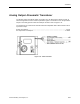
Because a laboratory ventilation system is a safety device, it must be designed and operated
to dilute and remove air contaminants in the laboratory and prevent those contaminants from
moving through the building. In addition, the ventilation system plays a role in regulating the
temperature of the laboratory room. The
Laboratory Control and Safety Solutions Application
Guide
, available from your local Siemens Building Technologies, Inc. representative,
introduces the issues and current design practices.
The following discussion of room pressurization applies to systems with a general exhaust
(Applications 2601 and 2603 for pneumatic actuation and Applications 2611 and 2613 for
electronic actuation). If Application 2602 for pneumatic actuation or Application 2612 for
electronic actuation is used, the situation is much simpler. The supply tracks the fume hood
exhaust, limited only by the supply maximum set point specified for each terminal.
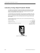
The LRC dynamically selects two airflow set points, SUP VOL STPT and GEX VOL STPT.
Through feedback control loops, the LRC adjusts the control dampers to drive the measured
flow values, SUP AIR VOL and GEX AIR VOL, to the set points.
The set points are selected to operate the room at the lowest airflows that meet the following
three goals. These goals are listed in order of priority.
1. Pressurize the room correctly.
2. Ventilate the room to dilute air contaminants.
3. Control the room temperature.
Under normal operating conditions, it is usually possible to achieve all three goals. However,
when conflicts arise, the controller’s highest priority is to correctly pressurize the room.
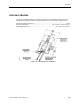
Correctly pressurizing the room means maintaining the selected difference between the total
supply flow and the total exhaust flow. That difference is calculated as follows:
VOL DIFFRNC = HOOD VOL + GEX AIR VOL + OTHER EXH - SUP AIR VOL - OTHER
SUP