
Operating Instructions
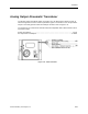

Controlling Laboratory Air Flow
Siemens Building Technologies, Inc. 3-3
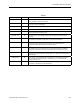
Table 3-1
Descriptor Number Function
VOL DIFFRNC 83 Difference between measured airflow into the room, and measured airflow out.
VOL DIFFRNC = Point 53 - Point 69
VOL DIF STPT 88 Desired value for the flow difference. This value can be selected and adjusted
to achieve room pressurization.
HOOD VOL 51 Airflow signal from the fume hood(s).
SUP AIR VOL 35 Measured value of the airflow delivered to the room by the supply terminal.
SUP FLO STPT 93 Desired value of the supply flow, chosen by the controller to achieve the
correct flow difference for the room.
GEX AIR VOL 30 Measured value of the airflow from the room through the general exhaust
terminal.
GEX FLO STPT 85 Desired value of the general exhaust. The controller selects the lowest value
that will lead to adequate supply flow, and correct pressurization.
TOTL SUPPLY 69 Point 35 + Point 61. This is the measured value of the airflow delivered to the
room by the supply terminal plus the value of any supply airflows not
connected to the Laboratory Room Controller (LRC).
TOTL EXHAUST 53 Point 30 + Point 51 + Point 89. This value is the sum of the measured value of
the airflow from the room through the general exhaust terminal, the airflow
through the fume hoods, and any exhaust flows not connected to the LRC.
OTHER SUP 61 Value of any supply airflows not connected to the LRC. Must be entered to the
controller to account for flows it cannot detect (i.e., office spaces connected to
a laboratory).
OTHER EXH 89 Value of any exhaust airflows not connected to the LRC. Must be entered to
the controller to account for flows it cannot detect (i.e., snorkel exhausts,
canopy exhausts, etc.).
TEMP CTL VOL 9 Amount of supply airflow that the temperature control sequence determines is
necessary to regulate the room temperature.