
Operating Instructions

Siemens Building Technologies, Inc. 4-1
4
Controlling Laboratory Temperature
LRC Temperature Control System
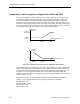
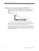
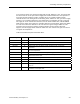
The temperature control system in the LRC has two main components, the room temperature
feedback calculations and the HVAC equipment sequencer. They interact as shown in Figure
4-1. The PID feedback calculations set the value of an intermediate point called TEMP
LOOPOUT. This value reflects the thermal load currently acting on the room. A value of
100% corresponds to the maximum need for cooling. A value of 0% corresponds to the
maximum need for heating. Based on that indication of load, the sequencer operates the
heating and cooling equipment for the room.
ROOM
STPT
TEMP
LOOPOUT
HVAC
Equipment
Sequencer
Room
Temperature
Sensor
Room
and
HVAC
PID
Feedback
Calculation
TEMP CTL VOL
(MIX DMPR CMD
OR VALVE CMD)
ROOM
TEMP
HEATING DEVICE
LAB0159R1
Figure 4-1. LRC Temperature Control System.
HVAC Sequencer
The HVAC equipment sequencer uses a set of sequencing points to tell the controller how to
adjust heating and cooling flows according to TEMP LOOPOUT. The values of the
sequencing points are selected when the LRC is applied to the room. These values are
selected to prevent simultaneous heating and cooling, and so that the heat flow from the
HVAC system varies as smoothly as possible across the range of TEMP LOOPOUT. The
specific meaning and values of the sequencing points depends on the heating and cooling
equipment used in the room.