
Operating Instructions

Laboratory Room Controller Owner's Manual
4-2 Siemens Building Technologies, Inc.
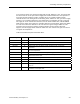
Temperature control sequence of Applications 2601 and 2611
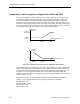
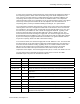
In the case of Applications 2601 and 2611, the sequencing points tell the controller how to
modulate the cooling airflow and reheat valve. They function as shown in the Figure 4-2.
When TEMP LOOPOUT is between REHEAT START and REHEAT END, the controller
operates in terminal reheat mode, using the hot water valve in the supply terminal to balance
the loads. It does this by setting the value of the point VALVE CMD. This value indicates the
percentage of valve actuator strokes from closed (0%) to open (100%). The valve command
is converted to the voltage that drives the valve actuator, REHEAT AO1.
TEMP CTL VOL
(POINT 9)
SUP MAX
(POINT 76)
SUP MIN
(POINT 77)
CFLO START
(POINT 5)
CFLO END
(POINT 6)
TEMP LOOPOUT (POINT 79)
VALVE CMD
(POINT 49)
100%
0%
REHEAT END
(POINT 8)
REHEAT START
(POINT 7)
TEMP LOOPOUT (POINT 79)
LAB0112R1
Figure 4-2. Temperature Control Sequence for Application 2601 and 2611.
When TEMP LOOPOUT is between CFLO START and CFLO END, the room operates in the
cooling mode, adjusting the point TEMP CTL VOL to balance the thermal loads. TEMP CTL
VOL indicates how much supply airflow is necessary to regulate the room temperature. The
supply flow to the room goes to this value when it is consistent with pressurization and
ventilation constraints. The actual supply flow (and the supply flow set point) may be more or
less than TEMP CTL VOL.
Setting CFLO START at or above REHEAT START prevents simultaneous heating and
cooling. In a typical Application 2601, the sequencing points are set as follows:
REHEAT END = 0%
REHEAT START = 50%
CFLO START = 50%
CFLO END = 100%