
Operating Instructions
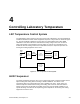

Controlling Laboratory Temperature
Siemens Building Technologies, Inc. 4-3
In some cases, temperature control performance can be improved by adjusting the values of
the sequencing points to better match the thermal sizing of the HVAC components in the
room. If there is any other heating or cooling equipment (such as perimeter radiation), the
sequencing values may be set to make room for the additional device. The temperature
control sequencing points are not included in any of the special purpose reports. They appear
near the top of the report that includes all the LRC subpoints. For more information on
sequencing points, consult your Siemens Building Technologies, Inc. representative.
The “Temp Control” subpoint report presents a picture of the current state of the temperature
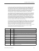
control system. There are a few typical scenarios that can be observed. In the first scenario,
the controller is in the cooling mode, meaning that the point VALVE CMD is set to zero, and
the value of the point TEMP CTL VOL is above the supply flow minimum. Typically, in this
mode, the measured value of the point SUP AIR VOL is close to TEMP CTL VOL. This
means that the thermal load is setting the supply flow. The measured supply flow may also
be substantially less than TEMP CTL VOL. This usually means that the supply flow is limited
by the need to keep the supply flow below the total exhaust. The general exhaust terminal
may be at its capacity, which is the limit of mechanical cooling.
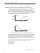
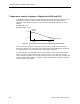
In the second scenario, the measured supply flow exceeds TEMP CTL VOL. This means that
the fume hoods are so far open that the supply flow needed to balance the room pressure is
more than the flow needed for cooling. Typically, this is not a stable condition and the LRC
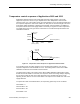
will move to the heating mode. In heating mode, TEMP CTL VOL goes to the supply
minimum and the reheat valve opens to whatever value it takes to keep the room
temperature at the setpoint. The actual supply flow may be at, or more, than TEMP CTL VOL.
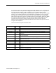
The LRC data needed to work with temperature control issues is found in the TEMP
CONTROL report. The points are described in Table 4-1.
Table 4-1.
Descriptor Number Function
ROOM TEMP 4 Value read from the room temperature sensor.
ROOM STPT 13 Desired value of the room temperature.
VALVE CMD 49 State of the reheat valve. Represents how far the valve is open.
REHEAT AO1 48 Voltage that drives the reheat valve, either directly or through a pneumatic transducer.
TEMP CTL VOL 9 Amount of supply flow that the controller calculates is necessary to regulate the room
temperature.
SUP AIR VOL 35 Measured value of the airflow through the supply terminal.
TEMP LOOPOUT 79 Value calculated by the room temperature PID algorithm. It indicates the thermal load
on the room.
ROOM P GAIN 63 Proportional feedback gain used to tune the room temperature control.
ROOM I GAIN 64 Integral feedback gain used to tune the room temperature control.
ROOM D GAIN 65 Derivative feedback gain used to tune the room temperature control.
ROOM BIAS 66 Starting point where the value of TEMP LOOPOUT goes when the controller turns on.
LOOP TIME 98 Time interval controls how often the LRC measures the room temperature and
calculates a new output value.