
Operating Instructions

Laboratory Room Controller Owner's Manual
4-4 Siemens Building Technologies, Inc.
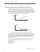
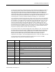
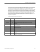
Temperature control sequence of Application 2602 and 2612
In Applications 2602 and 2612, the supply airflow must track the fume hood flow; there is no
opportunity to change the airflow to meet cooling demand. The sequencing function is
typically set up as shown in the Figure 4-3. This means the sequencing points are set as
follows:
REHEAT END = 0%
REHEAT START = 50%
VALVE CMD
(POINT 49)
100%
0%
REHEAT END
(POINT 8)
REHEAT START
(POINT 7)
TEMP LOOPOUT (POINT 79)
LAB0116R1
Figure 4-3. Temperature Control Sequence for Applications 2602 and 2612.
If there is any other heating or cooling device in the room, it may be accommodated by
adjusting the values of the sequencing points. Consult your Siemens Building Technologies,
Inc. representative for more information on using the sequencing points.
In normal operation, you will always observe VALVE CMD at some value between 0% and
100%. If the point reaches one of its limits, and stays there, then the thermal load on the
room is outside the capacity of the HVAC system to control it. (The valve may normally reach
its limits temporarily in response to a sudden change in thermal load. This does not indicate
that the system is overloaded).