
Operating Instructions

Controlling Laboratory Temperature
Siemens Building Technologies, Inc. 4-5
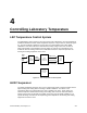
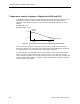
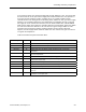
Temperature control sequence of Applications 2603 and 2613
Applications 2603 and 2613 covers rooms with dual-duct supply systems. The HVAC
equipment sequencer can be set up to implement the three temperature control modes
shown in Figure 4-4. In the cooling mode, the mixing damper is set to full cooling position and
the sequencer adjusts the value of the TEMP CTL VOL point as the load changes. This is the
mode where TEMP LOOPOUT is between CFLO START and CFLO END. The TEMP CTL
VOL point indicates how much supply airflow is necessary to regulate the room temperature.
The supply flow to the room goes to this value when it is consistent with pressurization and
ventilation constraints.
TEMP CTL VOL
(POINT 9)
SUP MAX
(POINT 76)
HFLO MAX
SUP MIN
(POINT 77)
CFLO START
(POINT 5)
HFLO
END
(POINT 8)
HFLO
START
(POINT 7)
CFLO END
(POINT 6)
TEMP LOOPOUT (POINT 79)
VALVE CMD
(POINT 49)
100%
0%
HFLO
START
(POINT 7)
CFLO
START
(POINT 8)
TEMP LOOPOUT (POINT 79)
LAB0115R1
Figure 4-4. Temperature Control Sequence for Applications 2603 and 2613.
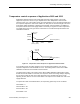
In the heating mode, the mixing damper is set to the full heating position. Here too, the
sequencer adjusts the value of TEMP CTL VOL. The heating mode is active when TEMP
LOOPOUT is between HFLO START and HFLO END.
The third mode is mixing. This mode is active when TEMP LOOPOUT falls between HFLO
START and CFLO START. In this mode, the sequencer moves the mixing damper, adjusting
the mix of the supply air from the hot and cold decks. If the thermal load can be met by
adjusting the mix, there is no need to add airflow. The sequencer sets TEMP CTL VOL to the
supply minimum.
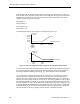
To operate the room as described above, the sequencing points may be set as follows:
HFLO END = 0
HFLO START = 30
CFLO START = 60
CFLO END = 100