
Operating Instructions

Laboratory Room Controller Owner's Manual
4-6 Siemens Building Technologies, Inc.
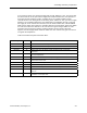
Some dual-duct HVAC designs do not include the heating mode described here. They mix
warm air with cold to reduce the cooling effect of the supply flow, but they do not increase the
supply flow to add heat to the room. The heating mode may be eliminated in the LRC by
setting the sequencing points as follows:
HFLO END = 0
HFLO START = 0
CFLO START = 50
CFLO END = 100
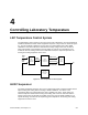
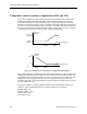
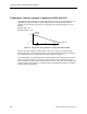
The resulting temperature control sequence is illustrated in Figure 4-5.
TEMP CTL VOL
(POINT 9)
SUP MAX
(POINT 76)
HFLO MAX
SUP MIN
(POINT 77)
CFLO START
(POINT 5)
HFLO
END
(POINT 8)
AND
HFLO START
(POINT 7)
CFLO END
(POINT 6)
TEMP LOOPOUT (POINT 79)
MIX DMPR CMD
(POINT 49)
100%
0%
HFLO
START
(POINT 7)
CFLO
START
(POINT 8)
TEMP LOOPOUT (POINT 79)
LAB0158R1
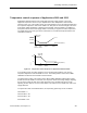
Figure 4-5. Adjusted Temperature Control Sequence for Applications 2603 and 2613.
In some cases, temperature control performance can be improved by adjusting the values of
the sequencing points to better match them to the thermal sizing of the HVAC equipment.
Consult your Siemens Building Technologies, Inc. representative for more information.
The “Temp Control” subpoint report presents the current state of the temperature control
system. There are a few typical scenarios that can be observed. In the first scenario, the
controller may be in cooling mode, meaning that MIX DMPR CMD is set to zero. When this
happens, the room is using all cold air, and no hot air. The value of TEMP CTL VOL is above
the supply flow minimum. Typically, in this mode, the measured value of SUP AIR VOL will
be close to TEMP CTL VOL. This means that the thermal load is setting the supply flow. The
measured flow may be substantially less than TEMP CTL VOL. In this case, the supply flow
is probably limited by the need to keep the supply flow below the total exhaust. The general
exhaust terminal may be at its capacity, which is the limit of mechanical cooling.