
Operating Instructions
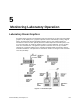

Laboratory Room Controller Owner's Manual
6-4 Siemens Building Technologies, Inc.
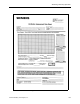
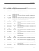
Address Descriptor Application Description
{44} DO4 2600
{44} GEX BLED DO4 2601, 2603 Drives a solenoid valve that moves a damper. Do not use or manually
set this point.
{44} SUP2 BLD DO4 2602 Drives a solenoid valve that moves a damper. Do not use or manually
set this point.
{44} GEX RETC DO4 2611, 2613 Drives a LAB AO-E module to retract electronic actuator. Do not use or
manually set this point.
{44} SUP2 RTC DO4 2612 Drives a LAB AO-E module to retract electronic actuator. Do not use or
manually set this point.
{45} DO5 2600
{45} OCC.UOC DO5 2601, 2602, 2603,
2611, 2612, 2613
Occupancy state of LRC; may drive light in room.
{46} DO6 2600
{46} SPARE DO6 2601, 2602, 2603,
2611, 2612, 2613
Spare DO termination.
{47} DO7 2600
{47} AUTOZERO DO7 2601, 2602, 2603,
2611, 2612, 2613
Drives the Autozero modules for calibrating the flow sensors. Do not
use or manually set this point.
{48} REHEAT AO1 2601, 2602 The voltage that drives the reheat valve, either directly or through a
pneumatic transducer.
{48} MIX AO1 2603 The voltage that drives the mixing damper actuator through a
pneumatic transducer.
{48} REHEAT AO1 2611, 2612 Voltage that directly drives the reheat valve.
{48} MIX AO1 2613 Voltage that directly drives the mixing damper actuator.
{49} VALVE CMD 2601, 2602, 2611,
2612
State of the reheat valve. Represents how far the valve is open.
{49} MIX DMPR CMD 2603, 2613 Position of the mixing damper. 100% means hot, 0% means cold.
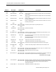
{50} DO8 2600
{50} ALARM DO8 2601, 2602, 2603,
2611, 2612, 2613
Intended to drive local alarm device (horn, light, etc.). Function set up
by setting alarm enable points.
{51} HOOD VOL 2601, 2602, 2603,
2611, 2612, 2613
Airflow signal from the fume hood(s).
52 MAX HOOD VOL 2601, 2602, 2603,
2611, 2612, 2613
Hood exhaust airflow value that corresponds to 10 volts on HOOD SIG
AI3. Must be setup to match the hood control equipment.
continued on the next page. . .
{53} TOTL EXHAUST 2601, 2602, 2603,
2611, 2612, 2613
Point 30 + Point 51 + Point 89. This value is the sum of the measured
value of the airflow from the room through the general exhaust terminal,
the airflow through the fume hoods, and any exhaust flows not
connected to the LRC.
54 FLOW COEFF 2 2600, 2602, 2612 Calibration parameter for airflow sensor.