
Treadmill User Manual

7ML19985GE01 SITRANS LC 500 – INSTRUCTION MANUAL Page 93
mmmmm
Appendix E
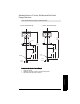
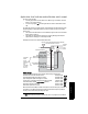
Application: level indicator and solid-state switch output
The loop current provides:
• a reading proportional to level, within the 0 - 100% range, at menu 00 or 10 on the
device, or at a remote indicator
• an out-of-range signal ooL alternating with PV if the level is above URV or below
LRV
The solid-state switch is activated at Upper Threshold Setting and deactivated at Lower
Threshold Setting. In the diagram below, it is used to activate a pump via an auxiliary
power circuit.
• The activation and deactivation can be modified by Upper and/or Lower Threshold
delays (menus 13 and 14).
• The reading can be stabilized if necessary by applying Damping (menu 0A): the
update value for Damping is controlled by menu 09.
Example: The level is to be held between 90% and 8%.
Device settings:
(The device is first restored to factory settings before being commissioned)
TV0 selected: Transmitter Variable 0 is PV Menu 01 reads Pv = 0
Lower Range Value (0% of range) is set to 14.3 Menu 0E reads 14.30
Upper Range Value (100% of range) is set to 75.8. Menu 0F reads 75.80
Current loop is in analog mode, with both buttons pressed Menu 07 reads C:An
Solid-state switch enabled, contact closed selected Menu 17 reads S:cc
1
Activation hysteresis is set to 90. Menu 15 reads 90.0
Deactivation hysteresis is set to 8. Menu 16 reads 08.0.
When the level reaches 90%, the solid-state output is closed and the pump is started via
the auxiliary circuit. When the level drops to 8% the solid-state output is opened, the
auxiliary circuit is deactivated, and the pump stops.
1.
S:cc appears while the button is pressed. See menu 17 on page 70 for more details.
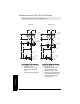
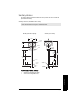
P
Indicator: primary variable viewed at menus 00 or 01;
units or% selected in menu 01
0-100%
auxiliary
power
pump
power
solid-
state
output
current loop connection
(menu 0F) URV = 100%
Upper Threshold Setting = 90%
menu 15 (activation hysteresis)
menu 16 (deactivation hysteresis)
Lower Threshold Setting = 8%
(menu 0E) LRV = 0%
(menu 0C) USL
(menu 0B) LSL
solid-state
switch
output:
selected at
menu 17
and
controlled
by menus
13 to 18.
75.8 pF
14.3 pF
Active Shield section