Operating and installation instructions LC 89950 GB
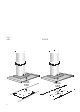
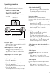
Fig. 1 GAZ Abb. 1 ELECTR. mind. 650 2 mind.
Instructions for use: Operating modes Appliance description Chimney panelling Light switches Light Fan switches Filter grille Operating modes Exhaust-air mode: ❑ The extractor-hood fan extracts the kitchen vapours and conveys them through the grease filter into the atmosphere. ❑ The grease filter absorbs the solid particles in the kitchen vapours. ❑ The kitchen is kept almost free of grease and odours.
Before using for the first time Important notes: ❑ The Instructions for Use apply to several versions of this appliance. Accordingly, you may find descriptions of individual features that do not apply to your specific appliance. ❑ This extractor hood complies with all relevant safety regulations. Repairs should be carried out by qualified technicians only. Improper repairs may put the user at considerable risk.
Operating procedure The most effective method of removing vapours produced during cooking is to: ❑ Switch the ventilator ON as soon as you begin cooking. ❑ Switch the ventilator OFF a few minutes after you have finished cooking. Display for fan setting Switching the fan OFF: ❑ Keep pressing the – button until the fan switches off. The displayed { goes out shortly afterwards. Ü Intensive setting: Maximum power is obtained at the intensive setting. It is only required for short intervals.
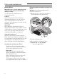
Filters and maintenance Grease filters: Metal filters are used to trap the greasy element of the vapours that develop during cooking. The filter mats are made from noncombustible metal. Caution: As the filter becomes more and more saturated with grease, not only does the risk of it catching fire increase but the efficiency of the extractor hood can also be adversely affected.
Filters and maintenance Activated carbon filter: For neutralizing odours in recirculating mode. Saturation indicator: ã When the activated carbon filter reaches saturation point, an acoustic signal is sounded for 10 seconds after the fan has switched off, and a ã appears in the display. The activated carbon filter should be replaced straight away. Inserting the filter: Warning: The halogen bulbs must be switched off and cool. 1.
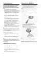
Cleaning and care Replacing the light bulbs Disconnect the extractor hood from the electricity supply by pulling out the mains plug or switching it off at the fuse box. ❑ At the same time as you clean the grease filters, clean off any grease from all accessible parts of the housing. This significantly reduces the fire hazard and ensures that the extractor hood performs as effectively as possible. ❑ Use a hot detergent solution or a mild window cleaner to clean the canopy of the extractor hood.
Setting the saturation indicator If you encounter a problem If it becomes necessary to change the operating mode (exhaust-air/recirculating mode), the saturation indicator for the filters must also be altered (see Installation Instructions). If an # or ã appears in the display: ❑ See "Filters and maintenance" Section. If is not possible to operate the extractor hood: ❑ Disconnect the extractor hood from the mains electricity supply by pulling out the plug or switching it off at the main fuse box.
Installation Instructions: Important information Old appliances are not worthless rubbish. Valuable raw materials can be reclaimed by recycling old appliances. Before disposing of your old appliance, render it unusable. You received your new appliance in a protective shipping carton. All packaging materials are environmentally friendly and recyclable. Please contribute to a better environment by disposing of packaging materials in an environmentally-friendly manner.
Prior to installation Exhaust-air mode mind. 36 560 120 150 120 150 700-1080 mind .128 600 280 350 380 374 520 The exhaust air is discharged upwards through a ventilation shaft or directly through the outside wall into the open. D Exhaust air should neither be directed into a smoke or exhaust flue that is currently used for other purposes, nor into a shaft that is used for ventilating rooms in which stoves or fireplaces are also located.
Prior to installation For optimum extractor hood efficiency: ❑ Short, smooth air exhaust pipe. ❑ As few bends in the pipe as possible. ❑ Diameter of pipe to be as large as possible and no tight bends in pipe. If long, rough exhaust-air pipes, many pipe bends or smaller pipe diameters are used, the air extraction rate will no longer be at an optimum level and there will be an increase in noise. ❑ Round pipes: We recommend Internal diameter: 150 mm (at least 120 mm).
Prior to installation Electrical connection Preparing the wall WARNING: THIS APPLIANCE MUST BE EARTHED IMPORTANT: Fitting a Different Plug: The wires in the mains lead are coloured in accordance with the following code: Green and Yellow – Earth Blue – Neutral Brown – Live If you fit your own plug, the colours of these wires may not correspond with the identifying marks on the plug terminals. This is what you have to do: 1.
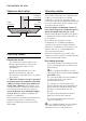
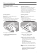
Installation This extractor hood is intended to be mounted onto the kitchen wall. 1. Remove the grease filter (refer to Operating Instructions). 2. Draw a line on the wall from the ceiling to the lower edge of the hood at the centre of the location where the hood is going to be mounted. 3. Use the template to mark the points on the wall where the screws will be mounted. In order to make it easier to hook the hood onto the screws, draw the outline of the area where the hood will be attached.
Installation 07. Screw in lower screws (hex screws). If any pressure is exerted on the glass screen when tightening the screws it could lead to glass breakage. 08. Stick protective film over the holes of the 2 lower mounting bolts in the protective grid. 13. Insert the complete flue duct at an angle into the glass shield and swivel backwards. Warning: The holes in the flue duct must be positioned exactly over the switches. 3. 1. 2. 2. 1. 14.
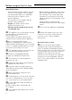
1 2x 2 10x 3 LZ51550 4 5 2x 6 360732 Siemens-Electrogeräte GmbH 5750 206 985 Printed in Germany 0404 Es.