
Installation Instructions


Document No. 565-919
Installation Inst ructions
May 16, 2007
Expected Installation Times
7 minutes.
Required Tools and Materials
•Flat-bladesc
rewdriver (1/8-inch blade width).
• Wire strippers.
• Cabling and connectors. See the Connecting
theAllen-BradleyDF1Drivertothe
Allen-Bradley System section.
CAUTION:
Always wear an electro-static discharge
wrist strap and discharge accumulated
static before touching field panel
components.
Prerequisites
•Driverhard
ware is installed a cco rdin g to its
respective
installation instru ction s.
• FLN Termination blocks insta lled, if any.
• One 115V or 230V receptacle (depending on
device) to power the Trunk Interface II.
• One AC power
receptacle for each
communica
tion interface adapter or device.
Depending on the type of installation, ot her
prerequisites may have to be completed.
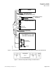
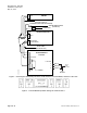
Connecting the Allen-Bradley DF1
Driver to the Allen-Bradley System
There are eigh
t w iring optio ns for configuring the
Allen-Bradl
ey DF1 Driver to the Allen-Bradley
System:
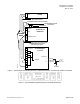
• PLC-5witha1785KEcardviaaTrunk
Interface II (Figure 1 and Figure 2)
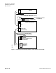
• PLC-5 (or SLC 5/04) using a 1770 KF2 module
viaaTrunkInterfaceII(Figure3andFigure4)
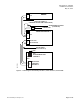
•PLC-5(orSLC
5/04) using a 1770 KF2 module
viaaTrunk/
RS-422 Interface (Figure 5 and
Figure 6)
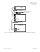
• SLC 5/03 via a Trunk Interface II (Figure 7)
• SLC 5/04 via a Trunk Interface II (Figure 8)
• SLC 5/05 via
a Trunk Interface II (Figure 9)
• CompactLogix or ControlLogix via a Trunk
Interface II (Figure 10)
Follow these steps to connect the Allen-Bradley DF1
Driver to the A llen-Bradley system:
1. Make cables
per diagram in F ig ure 1 and Figure 2,
Figure 3 and
Figure 4, Figure 5 and Figure 6,
Figure 7, Fi
gure 8, Figure 9, or Figure 10.
2. Install the Trunk Interface per diagram in Figure 1
andFigure 2, Figure 3 and Figure 4, Figure 5
and Figure 6, Figure 7, Figure 8, Figure 9, or
Figure 10.
3. Connect cables per diagram in Figure 1 and
Figure 2, Figure 3 and Figure 4, Figure 5
and Figure 6, Figure 7, Figure 8, Figure 9, or
Figure 10.
4. Plug in po
wer supply for the Trunk Interface
per diagr
am in Figure 1 andFigure 2, Figure 3
and Figur
e 4, Figure 5 and Figure 6, Figure 7,
Figure 8,
Figure 9, or Figure 10.
P
age 2 of 10
S
iemens Building Technologies, In c.