
Installation Instructions

Installation Instructions
Document No. 565-495
April 30, 2009
Staefa SMART D
river for PXC Modular
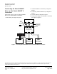
These installation instructions cover the connection
of th e Staefa SMART Driver to the Staefa SMART
II Controllers. For hardware installation of the PXC
Modular, see document number 553-638.
Product Description
The Staefa SMART Driver enables communication
between th e APOGEE
®
Automation System and the
Staefa SMART II Controllers.
Product Numbers
PXC00-PE96.A PXC Modular RS-485 or Ethernet
ALN, 96 FLN nodes
PXC00-E96
.A
PXC Modula
r with BACnet/IP
ALN and BA
Cnet MS/TP ALN,
96 FLN nod
es
PXC100-PE96.A PXC Modular RS-485 or Ethernet
ALN, TX-I/O Supp ort, 96 FLN
nodes
PXC100-E96.A PXC Modular BACnet/IP ALN
and BACnet MS/TP ALN, TX-I/O
Support, 96 FLN nodes
PXX-485
.3
Expansion Module, three RS-485
FLN connections
538–907
SMART TI-3 (TTL/RS-485)
Interface
LSM-INT-STFASMRT License for Staefa SMART Driver
Warning/Caution Notations
WARNING:
Personal injury/loss of life m ay occur if you
do not follow the procedures as specified.
CAUTION:
Equipment da
mage or loss of data m ay
occur if you d
o not follow the procedures
as specified.
Expected In
stallation Times
The expected installat i on time is 7 minutes.
Required Tools and Materials
• Flat-blade screwdriver (1/8-inch blade width).
• Wire stripp
ers.
• Cabling and connectors. See the Connecting
the Staefa SMART Driver to the Staefa
SMART II Controllers section.
CAUTION:
Always wear an electro-static discharge
wrist strap and discharge accumulated
static before touching field panel
components.
Prerequisites
• Driver hardware is installed according to its
respective installation instructions.
•FLNTermi
nation blocks installed, if any.
• One AC power receptacle for each
communication interface adapter or device.
Dependin
g on the type of installation, other
prerequi
sites may have to be completed.
I
tem Number: 565-495, Rev. AA
P
age 1 of 2