
Operating Instructions

Document No. 553-638
Installation Instructions
October 18, 2019
Page 2 of 4 Siemens Industry, Inc.
Energy Management Applications
For energy management only (low voltage Class 2), the
PXC Modular may be mounted on a flat surface.
Applications Requiring a Secure Enclosure
For any application requiring a secure enclosure, mount
the PXC Modular inside a listed enclosure along with a
Service Box and Sidewall Kit, if needed.
Modular Series Smoke Control
Application Requirements
CAUTION
The 115V or 230V PX Series Service Box
is required for UL864 and NFPA92A
compliant installations. For more
information, see the
PX Series Service
Box Assemblies Installation Instructions
(553-131) or the
Service Box Installation
Instructions
(586-135). For non-UL864
and non-NFPA92A applications, any 24
Vac Class 2 transformer can be used.
NOTE:
For smoke control applications over Ethernet or
BACnet/IP, the PXC Modular must be
connected to the Automation Level Network
(ALN) through an Ethernet switch that is UL
Listed for Fire Signaling. ALN and FLN circuits
are supervised.
For smoke control applications, mount the PXC Modular
inside a 19-inch or 34-inch PX Series enclosure (PXA-
ENC19 or PXA-ENC34). For more information, see the
19" and 34" PX Series Enclosure Assemblies
Installation Instructions (553-130).
• The controller must be located at the bottom of
the enclosure.
• The controller may be oriented either
horizontally or vertically.
• For Ethernet communications, a UL Listed
surge protector is required for Ethernet or
BACnet/IP networks. The surge protector must
be located in the same enclosure as the
controller.
For modems used with smoke control applications:
• The UL864 Listed surge protector is required.
• Devices connected between the USB port and
the UL Listed surge protector must be located
within the same room.
• A USB-to-RS-232 adaptor may be needed for
UL Listed modems or UL Listed printers that
are not configured for USB communication.
• The modem may be located inside the PX
Series enclosure.
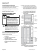
Figure 1: Smoke Control Layout for Modular with TX-I/O
Island Bus on Horizontal DIN Rails.
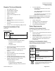
Figure 2: Smoke Control Layout for Modular with TX-I/O
Island Bus on Vertical DIN Rails