
Operating Instructions

Installation Instructions
Document No. 553-638
October 18, 2019
PXC Modular Series
Siemens Industry, Inc. Page 1 of 4
Item No. 553-638(GA)
Danger/Warning/Caution Notation
DANGER
Electric shock, death, or severe property
damage may occur if you do not perform a
procedure as specified.
WARNING
Personal injury or property damage may
occur if you do not follow a procedure as
specified.
CAUTION
Equipment damage or loss of data may
occur if you do not follow a procedure as
specified.
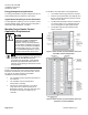
PXC Modular Series Product
Numbers
Product Number
Description
PXC00-E96.A
PXC Modular, BACnet/IP or MS/TP ALN, P1
or MS/TP FLN. PXX-485.3 is a connection
for FLN devices.
PXC00-PE96.A
PXC Modular, Ethernet/IP or RS-485 ALN,
P1 FLN. PXX-485.3 is also required as the
connection to the FLN devices.
PXC100-E96.A
PXC Modular, BACnet/IP or MS/TP ALN, P1
or MS/TP FLN, self-forming TX-I/O Island
Bus. PXX-485.3 is also required as the
connection to the FLN devices.
PXC100-PE96.A
PXC Modular, Ethernet/IP or RS-485 ALN,
P1 FLN, self-forming TX-I/O Island Bus.
PXX-485.3 is also required as the
connection to the FLN devices.
PXX-485.3
Provides FLN support for the PXC Modular.
Includes three RS-485 P1 FLN connections
or one MS/TP FLN connection; maximum of
96 devices supported.
PXA-DIN16KIT
Accessory kit with four 16-inch (406 mm)
DIN rails
For more information, see the TX-I/O Module
Installation Instructions (553-141) and TX-I/O Power
Supply and Bus Modules Installation Instructions (553-
142).
General Installation Requirements
CAUTION
All devices not isolated by an Island Bus
Expansion module (TXA1.IBE) must be
connected to the same grounding point.
CAUTION
TX-I/O components require a system
neutral with single point earth ground. Do
not connect these components to a
floating system neutral.
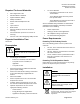
Service Box Earth Grounding of
System Neutral
System Neutral (⊥) must be continuous throughout the
TX-I/O bus.
• System Neutral is required to be earth-
grounded at a single point only.
• For a PXA Service Box: Connect the green wire
to the earth ground stud under the wire cover.
• For migrating with an MEC Service Box: The
earth ground is installed in the primary field
panel by a single external jumper between the
service box E terminal and N terminal.
• For a Third-party Transformer connect the
transformer secondary neutral to the building-
approved earth ground at the terminal block.
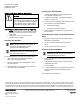
• When a separate 24Vac source is installed in
any secondary field panel isolate power using a
TXA1.IBE communication module in primary
and each secondary field panel.