
Installation Instructions

Installation Instructions
Document No. 553-654
October 18, 2019
TC Modular Series
Siemens Industry, Inc. Page 1 of 4
Item No. 553-654(FA)
Danger/Warning/Caution Notation
'
'$1*(5
(OHFWULFVKRFNGHDWKRUVHYHUHSURSHUW\
GDPDJHPD\RFFXULI\RXGRQRWSHUIRUP
DSURFHGXUHDVVSHFLILHG
:
:$51,1*
3HUVRQDOLQMXU\RUSURSHUW\GDPDJHPD\
RFFXULI\RXGRQRWIROORZDSURFHGXUHDV
VSHFLILHG
&
&$87,21
(TXLSPHQWGDPDJHRUORVVRIGDWDPD\
RFFXULI\RXGRQRWIROORZDSURFHGXUHDV
VSHFLILHG
TC Modular Series Product Numbers
3
3URGXFW1XPEHU
'
'HVFULSWLRQ
7&(7 7&0RGXODU%$&QHW,3RU0673)/1
VHOIIRUPLQJ7;,2,VODQG%XV3;;
LVDOVRUHTXLUHGDVWKHFRQQHFWLRQWRWKH
)/1GHYLFHV
3;; 3URYLGHV)/1VXSSRUWIRUWKH7&0RGXODU
,QFOXGHVRQH0673)/1FRQQHFWLRQ
PD[LPXPRIGHYLFHVVXSSRUWHG
3;$',1.,7 $FFHVVRU\NLWZLWKIRXULQFKPP
',1UDLOV
For more information, see the TX-I/O Module
Installation Instructions (553-141) and TX-I/O Power
Supply and Bus Modules Installation Instructions (553-
142).
General Installation Requirements
&
&$87,21
$OOGHYLFHVQRWLVRODWHGE\DQ,VODQG%XV
([SDQVLRQPRGXOH7;$,%(PXVWEH
FRQQHFWHGWRWKHVDPHJURXQGLQJSRLQW
&
&$87,21
7;,2FRPSRQHQWVUHTXLUHDV\VWHP
QHXWUDOZLWKVLQJOHSRLQWHDUWKJURXQG'R
QRWFRQQHFWWKHVHFRPSRQHQWVWRD
IORDWLQJV\VWHPQHXWUDO
Service Box Earth Grounding of System
Neutral
6\VWHP1HXWUDOPXVWEHFRQWLQXRXVWKURXJKRXWWKH
7;,2EXV
z 6\VWHP1HXWUDOLVUHTXLUHGWREHHDUWKJURXQGHGDW
DVLQJOHSRLQWRQO\
z )RUD3;$6HUYLFH%R[&RQQHFWWKHJUHHQZLUHWR
WKHHDUWKJURXQGVWXGXQGHUWKHZLUHFRYHU
z )RUD7KLUGSDUW\7UDQVIRUPHUFRQQHFWWKH
WUDQVIRUPHUVHFRQGDU\QHXWUDOWRWKHEXLOGLQJ
DSSURYHGHDUWKJURXQGDWWKHWHUPLQDOEORFN
z :KHQDVHSDUDWH9DFVRXUFHLVLQVWDOOHGLQDQ\
VHFRQGDU\ILHOGSDQHOLVRODWHSRZHUXVLQJD
7;$,%(FRPPXQLFDWLRQPRGXOHLQSULPDU\DQG
HDFKVHFRQGDU\ILHOGSDQHO
Energy Management Applications
)RUHQHUJ\PDQDJHPHQWRQO\ORZYROWDJH&ODVV
WKH7&0RGXODUPD\EHPRXQWHGRQDIODWVXUIDFH
Applications Requiring a Secure
Enclosure
)RUDQ\DSSOLFDWLRQUHTXLULQJDVHFXUHHQFORVXUH
PRXQWWKH7&0RGXODULQVLGHDOLVWHGHQFORVXUHDORQJ
ZLWKD6HUYLFH%R[DQG6LGHZDOO.LWLIQHHGHG
Document No. 553-654
Installation Instructions
October 18, 2019
,QIRUPDWLRQLQWKLVGRFXPHQWLVEDVHGRQVSHFLILFDWLRQVEHOLHYHGFRUUHFWDWWKHWLPHRISXEOLFDWLRQ7KHULJKWLVUHVHUYHGWRPDNHFKDQJHVDVGHVLJQ
LPSURYHPHQWVDUHLQWURGXFHG7$/21LVDUHJLVWHUHGWUDGHPDUNRI6LHPHQV,QGXVWU\,QF'HVLJRpDQG'HVLJRp&&DUHUHJLVWHUHGWUDGHPDUNVRI
6LHPHQV6FKZHL]$*2WKHUSURGXFWRUFRPSDQ\QDPHVPHQWLRQHGKHUHLQPD\EHWKHWUDGHPDUNVRIWKHLUUHVSHFWLYHRZQHUVk6LHPHQV
,QGXVWU\,QF$OOSUHVHQWHGRIIHULQJVDUHVXEMHFWWRDF\EHUVHFXULW\GLVFODLPHUZKLFKLVDYDLODEOHDWZZZVLHPHQVFRPEWF\EHUVHFXULW\
6
6LHPHQV,QGXVWU\,QF
6PDUW,QIUDVWUXFWXUH
'HHUILHOG3DUNZD\
%XIIDOR*URYH,/
86$
7HO
<RXUIHHGEDFNLVLPSRUWDQWWRXV,I\RXKDYHFRPPHQWVDERXWWKLVGRFXPHQW
SOHDVHVHQGWKHPWR6%7BWHFKQLFDOHGLWRUXVVEW#VLHPHQVFRP
'RFXPHQW1R
3ULQWHGLQWKH86$
3
3DJH
RI
Class 1 and Class 2 Wiring Separation
&$87,21
8//LVWLQJVUHTXLUHWKDW1(&&ODVV,DQG
&ODVV,,ZLULQJEHNHSWVHSDUDWHIURPHDFK
RWKHU8VHVHSDUDWHFRQGXLWDQGFDEOHWLH
EDUVWRVHSDUDWH&ODVV,'LJLWDO2XWSXW
'2ZLUHVIURPDOORWKHU&ODVV,,ZLULQJ
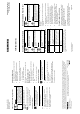
Removing the Connector Covers (If
required)
127(
'RQRWUHPRYHFRYHUVIURPWKHXQXVHG7;,2
EXVFRQQHFWRUVDWWKHHQGVRIWKHVHOIIRUPLQJEXV
¾ Remove the connector covers from the
hardware being installed.
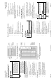
Installing the DIN Rail
127(6
$OORZDPLQLPXPFOHDUDQFHRILQFKHV
FPDURXQGWKHILHOGSDQHOSRUWVDQG
FRQQHFWRUVIRUWHUPLQDWLQJZLUHV
)RUORQJHU',1UDLOVXVHRQHPRXQWLQJVFUHZ
SHUUXQQLQJIRRWRI',1UDLO
Do the following if the DIN rail is not already installed:
1. Align and level the DIN rail on the mounting
surface or enclosure backplane.
2. Mark the position of the mounting holes at either
end of the DIN rail.
3. Using wall anchors, if necessary, attach the DIN
rail to the surface or backplane.
Installing the TC Modular
1. If an Expansion Module is used, plug it into the TC
Modular Expansion bus.
2. Install the TC Modular and optional Expansion
Module on the DIN rail.
3. Connect one of the following devices to the TX-I/O
bus connector on the TC Modular:
x TX-I/O Power Supply
x TX-I/O Bus Connection Module
7KH7&0RGXODULVQRZDEOHWRFRPPXQLFDWHRQWKH
7;,2EXV
Connecting the Power and
Communication Wires
1. Plug in the 24 Vac power from the Service Box or
transformer terminal block.
2. Plug in the TX-I/O communication and power
wires.
3. Plug in the FLN connectors (if used).
Completing the Installation
127(
'RQRWFRQQHFWWKHQHWZRUNFRPPXQLFDWLRQ
FDEOHXQWLOVWDUWXSLVFRPSOHWH
1. Ensure that AC power is turned ON at the circuit
breaker panel.
2. Turn the power switch ON at the Service Box or
transformer enclosure.
3. Verify the LEDs.
For more information, see the TC Modular Series
Product Diagram and TX-I/O Module Product Diagram.
The installation is now complete.