
Installation Instructions

Document No. 553-654
Installation Instructions
October 18, 2019
Siemens Industry, Inc. Page 3 of 4
Required Tools and Materials
x Wire stripper/side cutter
x Small flat-blade screwdriver
x Digital multimeter (DMM)
x Phillips screwdriver
x Electric drill and Phillips driver bit
x Level
x Tape measure
x Black marker
x Masonry drill bit (to mount on concrete or
masonry)
x Four wall anchors (to mount on concrete or
masonry)
x Four No. 8-18 x 3/8” self-tapping Phillips
screws
Expected Installation Time
20 minutes
Prerequisites
&
&$87,21
1RSRZHUZLULQJLVFRQQHFWHGWRWKH7&
0RGXODURURWKHU7;,2FRPSRQHQWVDW
WKLVWLPH
x If mounting in an enclosure:
Enclosure is installed, DIN rail included.
The power source is installed, as
applicable.
The power is OFF.
x All necessary wiring is pulled and terminated
per the layout drawing.
x Power and communication wiring is terminated
to the removable plugs supplied with the
devices.
x DIN rail is installed.
x Power requirements are met. See the Power
Requirements section.
x Common Ground requirements are met. See
the General Installation Requirements section.
x Optional requirements are met. See the
appropriate following sections:
Smoke Control
Energy Management Applications
Applications Requiring a Secure Enclosure
x For TX-I/O Modules:
Point wiring is terminated on the TX-I/O
Terminal Base.
TX-I/O Module labels have been printed
from System Profile.
TX-I/O Modules are either removed from
or parked in the terminal bases.
See the TALON Wiring Guidelines for Field Panels and
Equipment Controllers (588-581) for detailed
information on the following:
x Power requirements
x Setting up smoke control applications
x CE compliance wiring requirements
x TX-I/O Module wiring diagrams
Power Requirements
Powering TX-I/O Primary Panels
One of the following power sources is pulled to the
enclosure:
x 120 Vac, 60 Hz and terminated at the 115V PX
Series Service Box.
x 230 Vac, 50/60 Hz and terminated at the 230V
PX Series Service Box.
x 24 Vac, 50/60 Hz Class 1 power limited from a
third-party transformer and connected to a
terminal block.
Powering TX-I/O Expansion Panels
Power wiring is run from the transformer in the primary
panel to the expansion panel, if needed.
Installation
:
:$51,1*
7XUQ2))$&SRZHUDWWKH212))
VZLWFKLQWKH6HUYLFH%R[RUWUDQVIRUPHU
HQFORVXUH
&
&$87,21
'RQRWLQVWDOOWKH7&0RGXODURQD
YLEUDWLQJVXUIDFHIRUH[DPSOHDQDLU
KDQGOHURUGXFWZRUN
7KLVGHYLFHLQFOXGHVHOHFWULFDODQGHOHFWURQLF
FRPSRQHQWVDQGPXVWQRWEHGLVSRVHGRIDV
GRPHVWLFZDVWH3URGXFWUHFRYHU\DQG
GLVSRVDOPXVWFRPSO\ZLWKDOOQDWLRQDODQG
ORFDOUHJXODWLRQV
Document No. 553-654
Installation Instructions
October 18, 2019
Page 2 of 4 Siemens Industry, Inc.
Modular Series Smoke Control
Application Requirements
&
&$87,21
7KH9RU93;6HULHV6HUYLFH%R[
LVUHTXLUHGIRU8/DQG1)3$$
FRPSOLDQWLQVWDOODWLRQV)RUPRUH
LQIRUPDWLRQVHHWKH
3;6HULHV6HUYLFH
%R[$VVHPEOLHV,QVWDOODWLRQ,QVWUXFWLRQV
RUWKH
6HUYLFH%R[,QVWDOODWLRQ
,QVWUXFWLRQV
)RU QRQ8/
DQGQRQ1)3$$DSSOLFDWLRQVDQ\
9DF&ODVVWUDQVIRUPHUFDQEHXVHG
1
127(
)RUVPRNHFRQWURODSSOLFDWLRQVRYHU
(WKHUQHWRU%$&QHW,3WKH7&0RGXODU
PXVWEHFRQQHFWHGWRWKH$XWRPDWLRQ
/HYHO1HWZRUN$/1WKURXJKDQ(WKHUQHW
VZLWFKWKDWLV8//LVWHGIRU)LUH6LJQDOLQJ
$/1DQG)/1FLUFXLWVDUHVXSHUYLVHG
For smoke control applications, mount the TC Modular
inside a 19-inch or 34-inch PX Series enclosure (PXA-
ENC19 or PXA-ENC34). For more information, see the
19" and 34" PX Series Enclosure Assemblies
Installation Instructions (553-130).
x The controller must be located at the bottom of
the enclosure.
x The controller may be oriented either
horizontally or vertically.
x For Ethernet communications, a UL Listed
surge protector is required for Ethernet or
BACnet/IP networks. The surge protector must
be located in the same enclosure as the
controller.
For modems used with smoke control applications:
Modem Requirements
x The UL864 Listed surge protector is required.
x Devices connected between the USB port and
the UL Listed surge protector must be located
within the same room.
x A USB-to-RS-232 adaptor may be needed for
UL Listed modems or UL Listed printers that
are not configured for USB communication.
x The modem may be located inside the PX
Series enclosure.
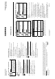
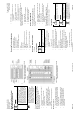
Figure 1: Smoke Control Layout for Modular with TX-I/O
Island Bus on Horizontal DIN Rails.
Figure 2: Smoke Control Layout for Modular with TX-I/O
Island Bus on Vertical DIN Rails.