
Installation Instructions

Document No. 565-712
Installation Instructions
November 12, 2013
Information in this document is based on specifications believed correct at the time of publication. The right is reserved to make changes as
design improvements are introduced. APOGEE and Insight are registered trademarks of Siemens Industry, Inc. Other product or company
names mentioned herein may be the trademarks of their respective owners. © 2013 Siemens Industry, Inc.
Siemens Industry, Inc.
Building Technologies Division
1000 Deerfield Parkway
Buffalo Grove, IL 60089-4513
USA
Tel. 1 + 847-215-1000
Your feedback is important to us. If you have
comments about this document, please send them
to SBT_technical.editor.us.sbt@siemens.com.
Document No. 565-712
Printed in the USA
Page 2 of 2
Required Tools and Materials
Flat-blade screwdriver (1/8-inch blade width).
Wire strippers.
Cabling and connectors. See the
Connecting the
Driver to the
Johnson Controls N2 Trunk
section.
CAUTION
Always wear an electro-static discharge
(ESD) wrist strap and discharge
accumulated static before touching field
panel components.
Prerequisites
Driver hardware is installed according to its
respective installation instructions.
FLN Termination blocks installed, if any.
Depending on the type of installation, other
prerequisites may have to be completed.
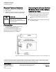
Connecting the Johnson Controls
N2 Master Driver to the Johnson
Controls N2 Trunk
Follow these steps to connect the Johnson Controls
N2 Master Driver to the Johnson Controls devices:
1. Disconnect the N2 Trunk from the Johnson
Controls Field Panel (NCU, NCM, N30, N31,
etc.).
2. Connect the N2 Trunk to the Driver as shown in
the following Figure.
Figure 1: Connecting the Johnson Controls N2 Master Driver to the Johnson Controls N2 Trunk.