
Operating Instructions

Document No. 553-638
Installation Instructions
October 18, 2019
Information in this document is based on specifications believed correct at the time of publication. The right is reserved to make changes as design
improvements are introduced. APOGEE and Insight are registered trademarks of Siemens Industry, Inc. Desigo® and Desigo® CC are registered
trademarks of Siemens Schweiz AG. Other product or company names mentioned herein may be the trademarks of their respective owners. © 2019
Siemens Industry, Inc. All presented offerings are subject to a cyber security disclaimer which is available at: www.siemens.com/bt/cyber-security.
Siemens Industry, Inc.
Smart Infrastructure
1000 Deerfield Parkway
Buffalo Grove, IL 60089-4513
USA
Tel. 1 + 847-215-1000
Your feedback is important to us. If you have comments about this document,
please send them to SBT_technical.editor.us.sbt@siemens.com.
Document No. 553-638
Printed in the USA
Page 4 of 4
Class 1 and Class 2 Wiring Separation
CAUTION
UL Listings require that NEC Class 1 and
Class 2 wiring be kept separate from each
other. Use separate conduit and cable tie
bars to separate Class 1 Digital Output
(DO) wires from all other Class 2 wiring.
Removing the Connector Covers (If required)
NOTE: Do not remove covers from the unused
TX-I/O bus connectors at the ends of the self-
forming bus.
➢ Remove the connector covers from the
hardware being installed.
Installing the DIN Rail
NOTE:
Allow a minimum clearance of 3 inches (7.6
cm) around the field panel ports and
connectors for terminating wires.
NOTE:
For longer DIN rails, use one mounting screw
per running foot of DIN rail.
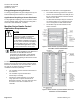
Do the following if the DIN rail is not already installed:
1. Align and level the DIN rail on the mounting
surface or enclosure backplane.
2. Mark the position of the mounting holes at either
end of the DIN rail.
3. Using wall anchors, if necessary, attach the DIN
rail to the surface or backplane.
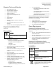
Installing the PXC Modular
1. If an Expansion Module is used, plug it into the
PXC Modular Expansion bus.
2. Install the PXC Modular and optional Expansion
Module on the DIN rail.
3. Connect one of the following devices to the TX-I/O
bus connector on the PXC Modular:
• TX-I/O Power Supply
• TX-I/O Bus Connection Module
4. The PXC Modular is now able to communicate on
the TX-I/O bus.
4.
Connecting the Power and Communication
Wires
1. Plug in the 24 Vac power from the Service Box or
transformer terminal block.
2. Plug in the TX-I/O communication and power
wires.
3. Plug in the FLN connectors (if used).
4.
Completing the Installation
NOTE:
Do not connect the network communication
cable until start-up is complete.
1. Ensure that AC power is turned ON at the circuit
breaker panel.
2. Turn the power switch ON at the Service Box or
transformer enclosure.
3. Verify the LEDs.
4. For more information, see the PXC Modular Series
Product Diagram and TX-I/O Module Product
Diagram.
The installation is now complete.