
Installation Instructions

Installation Instructions
Document No. 565-495T
July 31, 2009
Staefa SMART D
river for TC Modular
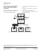
These installation instructio n s cover the connec tio n
of the Staefa SMART Driver to the Stae fa S MART
II Controlle rs. F or hardware installation o f the TC
Modular, see document number 553-654.
Product Description
The Staefa SMART Driver enables communication
between the TALON
®
Automation System and the
Staefa SMART II Controllers.
Product Numbers
TC1000-E96.T TC Modular BACn et/IP a nd
BACnet MS/TP ALN, 96 FLN
nodes
PXX-485.3 Expansion Module, three
RS-485 FLN connections
538–907
SMART TI-3 (TTL/RS-485)
Interface
LSM-INT-STFASMRT.T License for Staefa SMART for
TC ModularDrive r
Warning/Caution Notations
WARNING:
Personal injury/loss of life m ay occur if you
do not follow the procedures as specified.
CAUTION:
Equipment damage or loss of data may
occur if you do not fo llow the procedure s
as specified.
Expected Installation Times
The exp ected
installation time is 7 minu tes.
Required Too
ls and Materials
• Flat-blade screwdriver (1/8-inch blade width).
• Wire strippers.
• Cabling and c
onnectors. See the Connecting
the Staefa SM
ART Driver to the Staefa
SMART II Con
trollers section.
CAUTION:
Always wear
an electro-static discharge
wrist strap
and discharge accumulated
static befo
re touching field panel
component
s.
Prerequis
ites
• Driver h ardware is installed accordin g t o its
respective installa tio n instruct ions.
• FLN Termination block s installed, if any.
•OneACpowe
r receptacle for each
communica
tion interface adapter or device.
Depending on the type of installation, o th e r
prerequisites may have to be completed.
I
tem Number: 565-495T, Rev. BA
P
age 1 of 2