
Installation Instructions

Document No. 565-495T
Installation Instructions
July 31, 200 9
Connecting the Staefa SMART
Driver to the Staefa SMART II
Controllers
Follow these steps to connect the Staefa SMART
Driver to the Staefa SMART II Controllers:
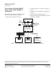
1. Make cables per diagram in F igure 1.
2. Install the SMART TI-3 Interface per diagram in
Figure 1.
3. If necess ary, in st all the SMVU-TI per diagram in
Figure 1.
4. Connect cables per diagram in Figure 1.
5. Plug in power supply for the SMART TI-3 Interface
per diagram in F igu re 1 .
RS-485 TRUNK CABLE
(MAX 4000’ / 1219.2 m;
STANDARD 24 AWG
LOW CAPACITANCE)
TAPE BACK
SHIELD
DO NOT
TAPE BACK
SHIELD
GROUND WIRE TO
EARTH (PN 538-583)
GW0762R2
POWER PACK
STAEFA SMART DRIVERS
S-+ S-+ S-
FLN1 FLN2 FLN3
+
SMART TI-3 INTERFACE
(TTL/RS-485 INTERFACE)
SMART I, SMKI, OR
SMART II CONTROLLER
TTL-485 TTL-485
RS-485 INTERFACE
TERMINAL BLOCK
22 21
TTL-485
S-+S-+S-
-
+
+
-
+
-
+
12
SMVU-V
TERMINAL BLOCK
SMART I, SMKI, OR
SMART II CONTROLLER
TERMINAL BLOCK
22 21
SMVU-TI
+-+-
LOW
HIGH
LOW
HIGH
LOW
HIGH
Figure 1. Connecting the Staefa SMART Driver to the Staefa SMART II Controllers.
Information in this document is based on specifications believed correct at the time of publication. The right is reserved to make changes as
design improveme nts are introduced. Product or company name s mentioned herein m ay be the trademarks of their respective owners.
© 2009 Siemens Building Technologies, Inc.
Siemens Building Technologies, Inc. Your feedb ack is important to us. If you have Document No. 565-495T
1000 Deerfield Parkway comments about this document, send them to Country of Origin: US
Buffalo Grove, IL 60089-4513 SBT_technical.editor.us.sbt@siemens.com.
Page 2 of 2
U.S.A.