
Installation Instructions

Installation Instructions
Document No. 565-1000
November 3, 2009
Trane Driver for PXC Modular
Item Number 565-1000, Rev. AA Page 1 of 3
These installation instructions only cover the
connection of the Trane Driver to the Trane System.
For hardware installation of the PXC Modular, see
PXC Modular Series Installation and Quick Start
(553-638).
Product Description
The Trane Driver enables communication between
the APOGEE
®
Automation System and the Trane
system.
Product Numbers
PXC00-PE96.A PXC Modular RS-485 or
Ethernet ALN, 96 FLN nodes
PXC00-E96.A PXC Modular BACnet/IP or
BACnet MS/TP ALN, 96 FLN
nodes
PXC100-PE96.A PXC Modular RS-485 or
Ethernet ALN, TX-I/O Support,
96 FLN nodes
PXC100-E96.A PXC Modular BACnet/IP or
BACnet MS/TP ALN, TX-I/O
Support, 96 FLN nodes
PXX-485.3 Expansion Module, three RS-
485 FLN connections
LSM-INT-TRANE License for Trane PXC Modular
Driver
Accessories
538-670 Trunk Interface II, 115V
538-675 Trunk Interface II, 230V
Warning/Caution Notations
WARNING:
Personal injury/loss of life may
occur if you do not follow the
procedures as specified.
CAUTION:
Equipment damage, or loss of
data may occur if you do not
follow the procedures as
specified.
Required Tools
• Flat-blade screwdriver (1/8-inch blade
width).
• Wire strippers.
• Cabling and connectors. See the
Connecting the Trane Driver to the Trane
System section.
Expected Installation Time
30 minutes
CAUTION:
Always wear an electro-static discharge
wrist strap and discharge accumulated static
before touching field panel components.
Prerequisites
• Driver hardware is installed according to its
respective installation instructions.
• FLN Termination blocks installed, if any.
• One 115V or 230V receptacle (depending
on device) to power the Trunk Interface II.
Depending on the type of installation, other
prerequisites may need to be completed.
Connecting the Trane Driver to the
Trane System
Follow these steps to connect the Trane Driver to the
Trane System:
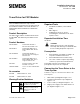
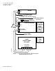
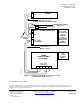
1. Make cables per diagram in Figure 1 or 2.
2. Install the Trunk Interface II per diagram in
Figure 1 or 2.
3. Connect cables per diagram in Figure 1 or 2.
4. Plug in power supply for the Trunk Interface II
per diagram in Figure 1 or 2.