
Installation Instructions

Installation Instructions
Document No. 565-714T
October 31, 2009
Veeder-Root D
river for TC Modular
These installation instructions cover the connection
of the Veeder-Root or the Veeder-Root Enterprise
Driver to the Veeder-Root system only. For hardware
installation of the TC Modular, see documen t number
553-654.
Product Description
The Veeder-Root driver enables communication
between the TALON
®
Automation System and the
Veeder-Root system.
Product Numbers
TC1000-E96.T TC Modular BA C net/IP and
BACnet MS/TP ALN, 96 FLN
nodes
PXX-485.3 Expansion Module, three
RS-485 FLN connections
LSM-INT-VR.T License for Veeder-Root TC
Modular Driver
LSM-INT-VRE.T License for Veeder-Root
Enterprise TC Modular Driver
Accessories
538-670
Trunk Interface II, 115V.
538-675
Trunk Interface II, 230V.
Warning/Caution Notations
WARNING:
Personal injury/loss of life may occur if you
do not follow the procedures as specified.
CAUTION:
Equipment damage or loss of data may
occur if you do not follow the procedures
as specified.
Expected Installation Times
The expe cted
installation tim e is 30 minutes.
Required Too
ls and Materials
• Flat-blade screwdriver (1/8-inch blade width).
• Wire strippers.
• Cabling and c
onnectors. See the Connecting
the Veeder-R
oot Driver to the Veeder-Root
Devices sec
tion.
CAUTION:
Always wear
an electro-static discharge
wrist strap
and discharge accumulated
static befo
re touching field panel
component
s.
Prerequis
ites
• Driver hardware is installed acco rding to its
respective installation instructions.
• FLN Termination blocks installed, if any.
Depending on the type of installation, other
prerequisites m ay have to be completed.
Connecting the Veeder-Root Driver
to the Vee
der-Root Devices
Follow these steps to connect the Veeder-Root Driver
to the Veeder-Root system:
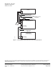
1. Make cabl
es per d iagram in Fig ure 1.
2. Connect cables per diagram in Figure 1.
I
tem Number: 565-714T, Rev. AA
P
age 1 of 2