
Installation Instructions

Document No. 565-802
Installation Instructions
November 21, 2006
Accessories
538-670
Trunk Interface II, 115V
538-675
Trunk Interfa
ce II, 230V
Warning/Caution Notations
WARNING:
Personal injury/loss of life may occur if you
do not follow the procedures as specified.
CAUTION:
Equipment d
amage or loss of data may
occur if you
do not follow the procedures
as specified
.
Expected I
nstallation Times
30 minutes.
Required Tools and Materials
• Flat-blade screwdriver (1/8-inch blade width).
• Wire strip
pers.
• Cabling and connectors. See the Connecting
the Veeder-Root Driver and Veeder-Root
Enterprise Driver to th e Veede r-Root S ystem
section.
CAUTION:
Always wear an electro-static discharge
wrist strap and discharge accumulated
static before touching field panel
components.
Prerequisites
• Driver hardware is installed according to its
respective installation instructions.
• FLN Terminati
on blocks installed, if any.
• One 115V or 230V receptacle (depending on
device) to power th e Trunk Interfac e II .
Dependingont
he type of installation, other
prerequisite
s may have to be completed.
Connecting t
he Veeder-Root Driver
and Veeder-Root Enterprise Driver
to the Veeder-Root System
Follow these steps to connect the Veeder-Root
Driver and Veeder-Root Enterprise Driver to the
Veeder-Root system:
For TCP/IP c
onnections to the Veeder-Root
system, do
not follow this procedure.
Instead, u
se IEEE 802.3 standard ethernet
connectio
ns and cabling to connect the
Veeder-Ro
ot Driver and Veeder-Root
Enterpri
se Driv er to the TCP/IP port (RJ-45
connecto
r on the TCP/IP Interface Module)
on the Vee
der-Root TLS Controller.
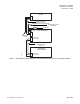
1. Make cables per diagram in Figu re 1.
2. Install t
he Trunk Interface II per diagram in
Figure 1.
3. Connect cables per diagram in Figure 1.
4. Plug in power supply for the Trunk Interface II per
diagram in Figure 1.
P
age 2 of 4
S
iemens Building Technologies, Inc.