
Data Sheet for Product

Technical Instructions M3FB…LX… Series Modulating Control Valve
Document Number CA2N4721E-P25 for Hot Gas Control
December 4, 2019
Page 2 Siemens Industry, Inc.
Ordering
The valve body and magnetic actuator form one integral unit and cannot be separated.
The M3FB...LX... valve and the ZM.../A module must be ordered separately.
When placing an order, specify the quantity, product number and product description.
Example :
1 M3FB15LX/A control valve and 1 ZM101/A module.
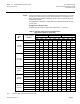
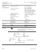
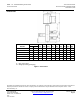
Table 1. Product Numbers.
Valve Product Number
(Without ZM...)
Line Size
[in]
Cv
AB → A
[gpm]
pmax
AB → A
SNA
[VA]
Pmed
[W]
[psi]
[bar]
M3FB15LX06/A
1/2
0.7
319
22
26
6
M3FB15LX15/A
1/2
1.8
319
22
26
6
M3FB15LX/A
1/2
3.5
319
22
26
6
M3FB20LX/A
3/4
5.9
261
18
26
6
M3FB25LX/A
1
9.4
174
12
40
10
M3FB32LX
1-1/4
14.0
116
8
40
10
Key :
pmax = Maximum admissible differential pressure across the valve’s control path (AB →
A valve) for the entire actuating range.
SNA = Rated apparent power for transformer selection.
Pmed = Typical power consumption.
Cv = Flow rate tolerance ±10%.
ZM Module Part
Number
Operating
Voltage
Control Signal
Working Range
ZM101/A
24 Vac
0 to 10 Vdc
4 to 8 Vdc
ZM121/A
24 Vac
4 to 20 mA
8 to 16 mA
Technical Design
The armature or magnetic core is designed as a floating component within the pressure
system, so that no external shaft gland is required. Therefore, leakage losses common
with moving parts are avoided. The valve cross-section allows for easy flow whether
the valve is fully or only partially open. This reduces pressure losses and ensures quiet
operation.
The valves are fitted with extended female solder unions, making pipe connections
easy.
Mechanical Design
The control signal is converted in the ZM.../A module into a phase cut signal, which
generates a magnetic field in the coil. This causes the only moving part, the armature,
to change its position in accordance with the interacting forces (magnetic field, counter-
spring, hydraulics, and so on). The armature responds rapidly to any change in signal,
transferring the corresponding movement directly to the control disc, enabling fast
changes in load to be corrected quickly and accurately.
The valve is normally closed. A spring closes the valve automatically if the power is
switched off or fails.