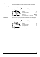
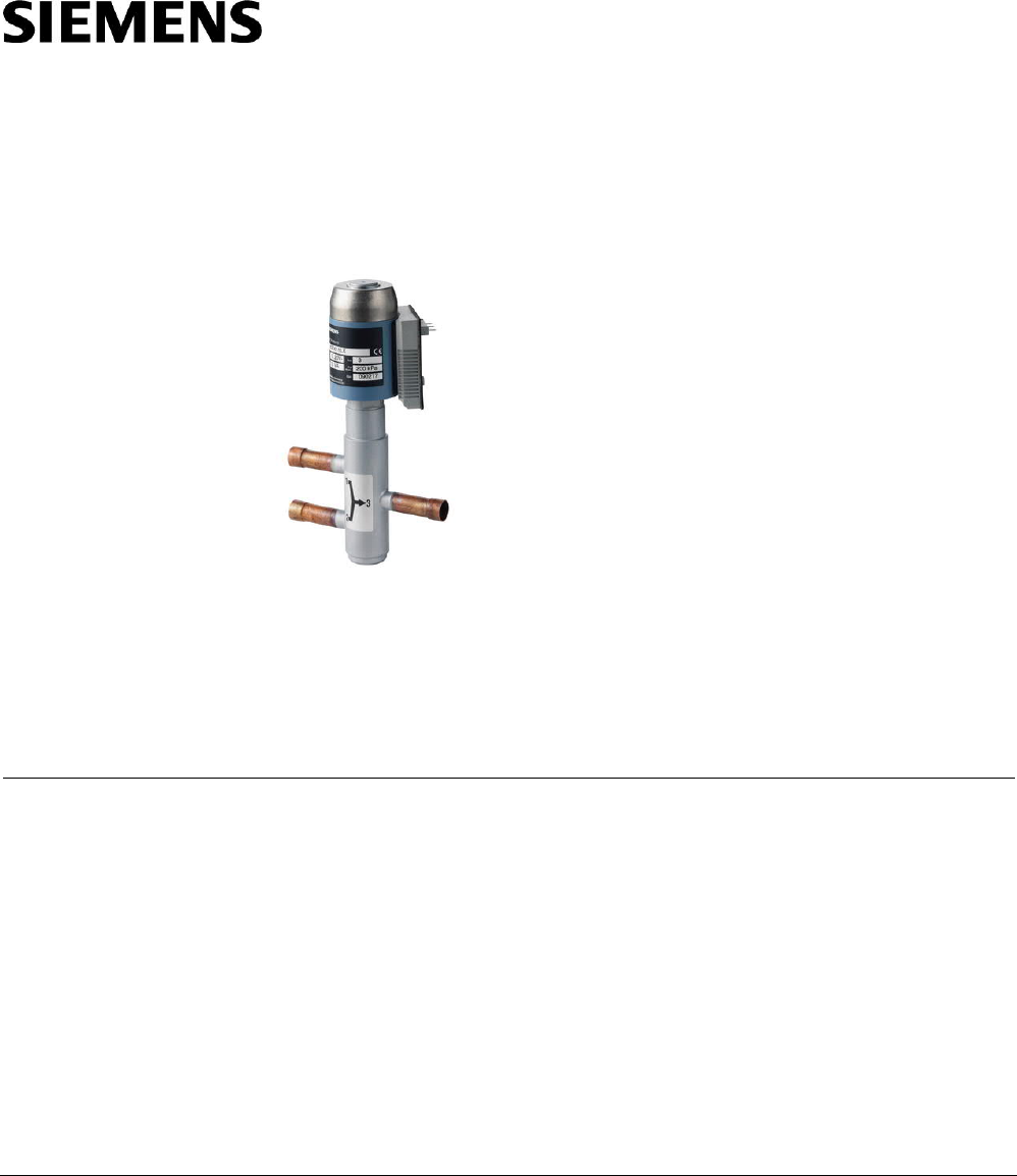
4 Modulating refrigerant valves with magnetic actuator, PN 32 722 M3FK..LX.. hermetically sealed, for condenser control · Mixing or straight-through valves with magnetic actuator for modulating capacity control of condensers. · Short positioning time (approx. 1 s) · High resolution · High rangeability · Hermetically sealed · Versatile electrical interface · Friction-free · Port 1 -> 3 closed when de-energized · Robust and maintenance-free Use The M3FK..LX..
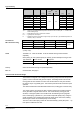
Type summary Type reference DN Dpmax kvs [m3/h] M3FK15LX06 M3FK15LX15 M3FK15LX 15 15 15 0.6 1.5 3.0 M3FK20LX M3FK25LX M3FK32LX 20 25 32 5.0 8.0 12.0 M3FK40LX M3FK50LX 40 50 20.0 30.0 Liquid Gas [MPa] [bar] 0.2 0.
Sizing Correct valve sizing (to ensure a sufficiently large pressure drop Dpv100 across the fully open valve) is the key to the correct operation of a refrigeration unit. All the components must be coordinated, and this can be ensured only by the refrigeration specialist. The application examples on pages 5 and show the recommended pressure drop in each case. Refrigeration capacity Q0 Selection table for approximate guide to valve size Pressure differential ∆pV100 = 0.5 bar across the fully-open valve.
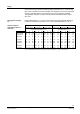
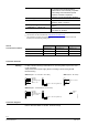
Selection chart 50320A Dp V [bar] 5 ] +2 t fl[°C +30 +35 +40 +45 +50 +55 +60 +65 0 1, 7 0, 5 4 0, 0, 3 0, +20 R134a (R12) tf l -10 +60 +40 2 0, [°C ] +10 +5 0 -5 V -15 D p -20 t0 [°C] -25 -30 -35 Dp V [bar] 0 1, 7 0, 5 4 0, 0, 3 0, 2 0, 0 1, 7 0, 5 4 0, 0, 3 0, 2 0, +20 +50 +55 +60 +65 t -10 [°C ] R407C (R22) +60 +40 fl +5°C ] t fl[°C +10 +5 0 -5 +25 +30 +35 +40 +45 -40 -15 t 0 [°C] -20 -25 -30 -35 -40 -10 -15 +60 +65 +45 +50 +55 Dp V [bar] l [°C ] R404A
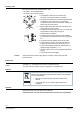
Application examples The diagrams shown here are principles only, without installation-specific details. 3-way hot-gas bypass control The heat recovery condenser is connected in parallel with the main condenser and is controlled on the liquid side by a mixing valve. Recommended pressure drop DpV100 across the fully-open valve (control path 1 ® 3) 0.
Mounting notes Mounting instructions are enclosed with the valve: · Nr. 35551 / A6V12108054 (valve) · Nr. 35541 (ZM.. terminal housing) 90° 4721Z02 4722Z01 90° Caution · The refrigerant valves can be mounted in any orientation, but upright mounting is preferable. · The pipes should be fitted such that the alignment does not distort the valve connections. The valve body should be fixed such that it cannot vibrate. Vibration can lead to burst connection pipes.
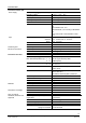
Technical data Functional actuator data Power supply Extra low-voltage only (SELV, PELV) Operating voltage 1) Frequency Typical power consumption Pmed Rated apparent power SNA Required fuse IF External supply line protection Input Positioning time Electrical connections Functional valve data Positioning signal Input resistance Input resistance Positioning time Cable entry Connection terminals Min. wire cross-section PN class Permissible operating pressure Max.
Environmental compatibility The product environmental declaration contains data on environmentally compatible product design and assessments (RoHS compliance, materials composition, packaging, environmental benefit, disposal).
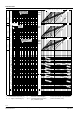
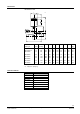
Dimensions Dimensions in mm A 9H702 C H3 B H2 1 H2 D 3 H1 2 L DN øD [mm] [inches] M3FK15LX06 15 5/8 150 57 25 164 60 73 67 2.6 M3FK15LX15 15 5/8 150 57 25 164 60 73 67 2.6 M3FK15LX 15 5/8 150 57 25 164 60 73 67 2.6 M3FK20LX 20 7/8 170 62 30 173 70 78 67 3.5 M3FK25LX 25 1 1/8 200 66 36 177 70 78 71 4.2 M3FK32LX 32 1 3/8 250 91 43 197 80 84 80 6.0 M3FK40LX 40 1 5/8 300 92 50 202 100 94 98 10.
Issued by Siemens Switzerland Ltd Smart Infrastructure Global Headquarters Theilerstrasse 1a 6300 Zug Switzerland Tel. +41 58-724 24 24 www.siemens.com/buildingtechnologies © Siemens Switzerland Ltd, 2010 Technical specifications and availability subject to change without notice.