
User's Manual


Siemens PLT 112 · 2002
2/5
System architecture
System software
■
Configuration
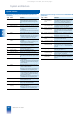
Listing of TELEPERM M standard function blocks
Data blocks
Blocks for analog and digital processing
Type Name Function
GA Data block for glo-
bal analog values
Storage of 256 analog values with error
10
-9
;
storage of process image, historical val-
ues etc.
GB Data block for glo-
bal binary values
Saving, scanning and linking of
256 binary values;
preferably for binary process inputs and
outputs
GM Data block for glo-
bal flags
Saving, scanning and linking of 256 inter-
nal binary statuses
GT Data block for glo-
bal times (timer)
Saving and generation of times/timers for
execution of time-dependent functions
FA Data field block for
analog values
Saving of internal/external analog values
with error 10
-9
; preferably for internal
results;
extension of GA block
FSA Data field block for
analog values
Saving of internal/external analog values
with error 10
-4
; preferably for internal
results
FB Data field block for
binary data
Saving of internal/external binary values;
extension of GB/GM blocks
FC Data field block for
characters
Saving of alphanumeric characters
(texts)
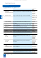
Type Name
Function
SUM Adder
Y = X1 + X2 - X3 - X4
MUL Multiplier
Y = X1 ⋅ X2
DIV Divider
Y = X1/X2
RAD Square root extrac-
tor
Y= sqrt (X) or
Y = K
⋅ sqrt (X)
LN Logarithm extractor
Y = KF ⋅ In | X |
EXP Exponential value
Y = e
x
ABS Absolute value X = | X |
INT Integrator
Y = K ⋅ integral (X) dt, K = 1/T
DIF Differentiator
Y(s)/X(s) = (T ⋅ s)/(1 + (T ⋅ s/v))
PT Delay
Y(s)/X(s) = 1/(1 + T ⋅ s)
TOZ Dead time
Y(s)/X(s) = e
-s ⋅ T
MIN Minimum-value
selection
Y = minimum of X1, X2, X3
MAX Maximum-value
selection
Y = maximum of X1, X2, X3
TOB Dead band
Y = X - TOBU for X < TOBU
Y = 0 for TOBU
≤ X ≤ TOBO
Y = X - TOBU for X > TOBO
PLG Progression block
Linear interpolation between 6 pairs of
turning points
GW Limit monitor
Limit check between 2 switching points
ASL Analog-value switch
Y = X1 for S = "0"
Y = X2 for S = "1"
SPEI Analog-value moni-
tor
Saving of max. 256 analog values
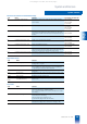
Blocks for binary processing
Type Name Function
VU AND
A = E1 AND E2 AND E3
VO OR
A = E1 OR E2 OR E3
VN Negation
A = NOT E
VM Flag
Flag of binary input signals (flip-flop)
VZ Time delay
Delay for switching on and off
VS +
STEP
STEP M block
Freely programmable in STEP M
MPX Multiplexer
To supply the STEP commands in the fol-
lowing VS/KS block
BW Binary selection
Selection of status combination from
max. 3 binary signals
INKU Increment converter
Converts analog values into opening or
closing pulses
BCE BCD input
Conversion of a BCD signal into an ana-
log value
BCA BCD output
Conversion of an analog value into a
BCD signal
KA Sequence start
Marks the beginning of an ON/OFF
branch of a subgroup control
KAK Sequence start
As KA, with additional functions
KB Sequence
Conditions of a control step, for power
plant systems
KBK Sequence
As KB, with additional functions
KS Sequence step
As KB, for process engineering systems
KV Sequence branch
Branching of a sequence into max. 6
branches, with process engineering sys-
tems
KE Sequence end
Last block in a sequence
KEK Sequence end
As KE, with additional functions
HA Auxiliary oil
Controls electric auxiliary oil pumps for
supply of bearing oil to aggregates
EAR Single analog-value
marshalling
Allocates analog values from block out-
puts in GA blocks
EBR Single bit marshal-
ling
Links individual binary outputs to GB/GM
data blocks
UBR Universal binary
marshalling
Links 16 binary blocks to GB/GM data
blocks
This catalog is out of date, see note on page 3