
User's Manual

Siemens PLT 112 · 2002
10/5
Data couplings with other systems
Direct couplings
Serial coupling
■
Overview
In certain cases it may be meaningful to accommodate comple-
te sections of an automation program in a subordinate automa-
tion level. This reduces the load on the automation system,
saving valuable computing time. This is particularly important for
automation tasks with short cycle times which place a high load
on the computing capacity of a CPU. Furthermore, subordinate
programs can also be generated and tested independent of
other parts of the program.
The following are required to couple the AS 488/TM automation
system with SIMATIC S5 S5-115U, S5-135U and S5-155U cen-
tral controllers as well as SIMATIC S7 S7-300 and S7-400 auto-
mation systems:
• Interface module for SIMATIC S5/S7 central controllers
• Connecting cable
• For SIMATIC S5:
CP 524 or CP 544 communications processor
See Catalog ST 50 for interface modules, parameterization
tools and accessories
• For SIMATIC S7-300:
CP 341 communications processor with 20-mA (TTY) interface
See Catalog ST 70 for interface modules, parameterization
tools and accessories
• For SIMATIC S7-400:
CP 441-2 communications processor
See Catalog ST 70 for interface modules, parameterization
tools and accessories
■
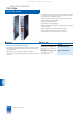
Design
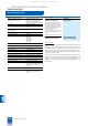
The interface module for SIMATIC S5/S7 central controllers,
6DS1 333-8AB, is a double-height compact assembly. The front
panel width is 30.48 mm (2 standard slots). The module has
2 backplane connectors for the I/O bus interface, and two serial
interfaces for connecting a SIMATIC S5/S7 central controller.
The interface module for SIMATIC S5/S7 central controllers can
be inserted into any slot for I/O modules of an AS 488/TM auto-
mation system or an ES 100 K extension system. SIMATIC S5/S7
central controllers can be connected to each of the two chan-
nels.
A shielded, four-wire cable twisted in pairs is used for data trans-
mission. The maximum permissible distance between the inter-
face module and the central controller is 1000 m. Data
exchange is via a serial coupling with 20-mA current loop. The
channel-specific transmission rate can be adjusted in steps:
■
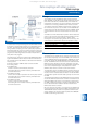
Mode of operation
The data arriving in parallel via the I/O bus of the automation sys-
tem are saved cyclically in the transfer RAM of the interface mo-
dule for SIMATIC S5/S7 central controllers. SIMATIC S7 central
controllers operate with SEND/RECEIVE and S5 analog value
format. The SIMATIC S5 central controllers can read the transfer
RAM using fetch telegrams. The send component of the inter-
face module reads the data from the transfer RAM, supplements
them into a complete telegram, and passes this on to the
SIMATIC S5/S7 central controller via the serial interface.
The telegrams sent by the SIMATIC S5/S7 central controller are
checked for reliability in the receive component of the interface
module, and the contained data are saved in the transfer RAM.
The automation system reads this data cyclically out of the trans-
fer RAM.
The data transfer between the AS 488/TM CPU and the interface
module for SIMATIC S5/S7 central controllers is handled via the
S5KS and S5KE driver blocks in the automation system. Either
the 3964 or 3964 R transmission procedure (selectable) is used
for the data transmission between interface module and SI-
MATIC S5/S7 central controller.
RK 512 is used as the protocol. In the process, the SIMATIC S5
central controller sends or fetches the data using telegrams. The
TELEPERM M interface module is the passive communication
station. SIMATIC S7 central controllers operate with SEND/RE-
CEIVE and S5 analog value format.
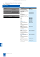
Transmission rate Max. cable length
300, 600, 1200, 2400 bit/s 1000 m
4800 bit/s 500 m
9600 bit/s 300 m
This catalog is out of date, see note on page 3