
User`s manual


User’s Manual
GPRS35 23 RTD Finland Oy
Chapter 5
B
OARD OPERATION AND PROGRAMMING
This chapter shows you how to program and use your GPRS35. It
provides a general description of the I/O map. Detailed serial port
programming tips are not within the scope of this manual.
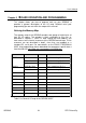
Defining the Memory Map
The memory map of the GPRS35 occupies two groups of eight bytes of
host PC I/O space. This window is freely selectable by the user as
described in
Chapter 2, Table 2-2.
After setting the base address you
have access to the internal resources of the GPRS35 control logic. These
resources are not described in detail, since they are mapped as a
standard PC serial port. For more details on the EXAR ST16C550IJ44
UART chip programming please download the component specific data t
from the website: http://www.exar.com/products/st16c550.html
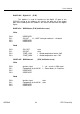
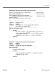
ADDR (hex) REGISTER DIR COMMENTS
TXD O Only if control reg. Bit 7=0
RXD I Only if control reg. Bit 7=0
BASE
BAUD div. Low Only if control reg. Bit 7=1
BAUD div. High Only if control reg. Bit 7=1BASE+1
IRQ enable Only if control reg. Bit 7=0
BASE+2 IRQ ID
BASE+3 Line control
BASE+4 Modem control
BASE+5 Line status
BASE+6 Modem status
BASE+400 Digital I/O I/O Digital I/O port
BASE+402 GSM status I/O Configuration registers
BASE+403 GSM control I/O Power control
Table 5-1a General I/O map of the GPRS35 UART