Structure and Use of the CPU ___________________ Preface Memory 1 ___________________ Documentation guide SIMATIC S7-1500 Structure and Use of the CPU Memory Function Manual 01/2013 A5E03461664-01 Memory areas and retentive 2 ___________________ memory Memory usage and 3 ___________________ application examples
Legal information Warning notice system This manual contains notices you have to observe in order to ensure your personal safety, as well as to prevent damage to property. The notices referring to your personal safety are highlighted in the manual by a safety alert symbol, notices referring only to property damage have no safety alert symbol. These notices shown below are graded according to the degree of danger.
Preface Purpose of the documentation This documentation describes the various memory areas of the S7-1500 CPU, and shows you how to make the best use of these memory areas. The manual also shows you how to free work memory by using recipes and Data Logs.
Preface Structure and Use of the CPU Memory 4 Function Manual, 01/2013, A5E03461664-01
Table of contents Preface ...................................................................................................................................................... 3 1 Documentation guide................................................................................................................................. 7 2 Memory areas and retentive memory ........................................................................................................ 9 3 2.1 CPU memory areas ........
Table of contents Structure and Use of the CPU Memory 6 Function Manual, 01/2013, A5E03461664-01
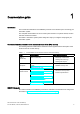
1 Documentation guide Introduction This modular documentation of the SIMATIC products covers diverse topics concerning your automation system. The complete documentation for the S7-1500 system consists of a system manual, function manuals and device manuals. The STEP 7 information system (Online Help) also helps you configure and program your automation system.
Documentation guide Structure and Use of the CPU Memory 8 Function Manual, 01/2013, A5E03461664-01
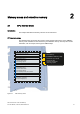
Memory areas and retentive memory 2.1 2 CPU memory areas Introduction This chapter describes the memory structure of S7-1500 CPUs. CPU memory areas The following figure shows the CPU memory areas and the load memory on the SIMATIC memory card. In addition to the load memory, the SIMATIC memory card may also contain other data, such as recipes, Data Logs and HMI backups.
Memory areas and retentive memory 2.1 CPU memory areas Load memory The load memory is a non-volatile memory for code blocks, data blocks, technology objects, and hardware configuration. When these objects are downloaded to the CPU they are first saved into load memory. This memory is located on the SIMATIC memory card. Note To run the CPU, a SIMATIC memory card must be inserted. Work memory The work memory is volatile memory that contains the code and data blocks.
Memory areas and retentive memory 2.1 CPU memory areas Information on memory areas in STEP 7 In STEP 7 you can view the offline and online information about the memory areas of your S7-1500 CPU. Offline: When you are creating or modifying a program, you can determine whether it is too large for a specific CPU. You can find this information under "Program information" in the project tree, for example.
Memory areas and retentive memory 2.1 CPU memory areas Additional memory areas Besides the memory areas that have been described for the user program and data, the CPU has additional memory areas available. The additional memory areas include the following: ● Bit memories, timers and counters ● Temporary local data ● Process images The CPU-specific sizes can be found in the technical specifications for the respective CPU.
Memory areas and retentive memory 2.2 Retentive memory areas 2.2 Retentive memory areas Introduction The S7-1500 CPUs have memory available for storing retentive data at POWER-OFF. Details about the size of the retentive memory can be found in the technical specifications for the CPU. In STEP 7, you can find the configured CPU's retentive memory utilization offline at "Program information > Resources" or online at Online & Diagnostics under "Diagnostics > Memory".
Memory areas and retentive memory 2.2 Retentive memory areas Tags from a global data block In a global data block, you can define either individual tags from a block or all of its tags collectively as retentive, depending on the setting for the "Optimized block access" attribute: ● "Optimized block access" activated: In the declaration table of the data block, you can define individual tags as retentive.
Memory areas and retentive memory 2.2 Retentive memory areas Tags of technology objects Certain tags of technology objects are retentive, for example adjustment values of absolute encoders. STEP 7 automatically manages the retentivity of technology object tags, so you do not have to configure their retentivity. The retentive tags of technology objects are unaffected by a memory reset. They can only be deleted by resetting to factory settings.
Memory areas and retentive memory 2.3 Summary of retentive behavior 2.3 Summary of retentive behavior Retentive behavior of the memory objects This chapter gives an overview of the retentive behavior of memory objects for S7-1500 CPUs. Besides the retentive memory areas described so far, there are additional objects with retentive behavior, such as the diagnostic buffer. These objects do not allocate any storage space in the retentive memory.
Memory areas and retentive memory 2.3 Summary of retentive behavior Diagnostic buffer With the S7-1500 CPUs, a portion of the diagnostic buffer is retentive. The number of retentive diagnostic buffer entries depends on the type of CPU. The latest entries in the diagnostic buffer are retained after power failure, and are not affected by a memory reset The retentive portion of the diagnostic buffer can only be deleted by resetting to factory settings.
Memory areas and retentive memory 2.4 Memory behavior when loading software changes 2.4 Memory behavior when loading software changes Introduction In the STOP and RUN modes of the S7-1500 CPU, you can load changes to the software without this affecting the actual values of tags already loaded. In STEP 7, you load changes to the software under "Download to device > Software (only changes)".
Memory areas and retentive memory 2.
Memory areas and retentive memory 2.
Memory usage and application examples 3.1 3 Memory usage for recipes Introduction A recipe represents a collection of parameter records with the same structure. These recipe data records are located in a non-runtime-relevant data block in the load memory, and do not occupy any storage space in the work memory. You have the option of reading individual recipe data records into a data block in work memory, and to access the data in the user program.
Memory usage and application examples 3.1 Memory usage for recipes Processing sequence ● Saving a recipe in load memory The various data records of a recipe are filled in a non-runtime-relevant DB in STEP 7 and then loaded to the CPU. In order to configure a non-runtime-relevant DB, you must activate the Only store in load memory" block attribute. Thus the recipes only use storage space in load memory, and not in work memory.
Memory usage and application examples 3.1 Memory usage for recipes Import and export of recipe data You have the option of exporting a recipe DB's recipe data records as a csv file, and of importing them from a csv file into a DB. The csv file is located in the "\recipes" directory of the SIMATIC memory card, and can be opened and processed further with a spreadsheet program such as Microsoft Excel. You can easily manage the csv files on the SIMATIC memory card using the CPU's web server (e.g.
Memory usage and application examples 3.1 Memory usage for recipes Reference You can find further information on the instructions for recipes in the online help for STEP 7 under "PLC programming > References > References (S7-1200/1500) > Extended instructions > Recipes and data logging > Recipe functions".
Memory usage and application examples 3.2 Memory usage for data logging 3.2 Memory usage for data logging 3.2.1 Overview of data logging Your controller program can store process values in Data Logs using the "Data Logging" instructions. The Data Logs are saved in csv format in the "\datalogs" directory of the SIMATIC memory card. The data records are organized in a circular Data Log of a predefined size.
Memory usage and application examples 3.2 Memory usage for data logging 3.2.2 Data structure of the data logs Introduction You use the "DataLogCreate" instruction to create a Data Log in STEP 7. The NAME parameter assigns the Data Log a name. The DATA and HEADER parameters specify the data type of all data elements in a Data Log data record and the header of the Data Logs. The RECORDS parameter indicates the maximum number of data records in the Data Logs.
Memory usage and application examples 3.2 Memory usage for data logging 3.2.3 Instructions for data logging Overview The following table gives an overview of the instructions for Data Logging. You will find the "Data Logging" instructionsin STEP 7 in the "Instructions" task card, under "Extended instructions > Recipe and data logging > Data Logging".
Memory usage and application examples 3.2 Memory usage for data logging Reference You can find further information on "Data Logging" instructions in the online help for STEP 7 under "PLC programming > References > References (S7-1200/1500) > Extended instructions > Recipes and data logging > Data Logging". 3.2.4 Example program for data logging This example program shows the storing of 3 process values for counter state, temperature, and pressure in a Data Log.
Memory usage and application examples 3.2 Memory usage for data logging Network 1 A rising edge at REQ starts the creation of the Data Log. Figure 3-5 Network 1 Network 2 Detect the output DONE from "DataLogCreate", because after the execution of "DataLogCreate" it is only set to 1 for a call. Figure 3-6 Network 2 Network 3 A rising edge triggers the point in time at which new process values are stored in the MyData structure.
Memory usage and application examples 3.2 Memory usage for data logging Network 4 The state of the input EN is based on the point in time at which the execution of "DataLogCreate" was completed. One execution of "DataLogCreate" extends over multiple cycles, and must be completed before a write operation is executed. The rising edge at input REQ is the event, that triggers an activated write operation. Figure 3-8 Network 4 Network 5 Close the Data Log once the last data record has been written.
Memory usage and application examples 3.2 Memory usage for data logging Network 6 A rising edge at the REQ input of the instruction "DataLogOpen" simulates the user pressing a button on an HMI device which opens a Data Log. If you open a Data Log in which all data records have been allocated process data, the next execution of the "DataLogWrite" instruction will overwrite the oldest data record. You can, however, also retain the old Data Log and instead create a new Data Log. This is shown in network 7.
Memory usage and application examples 3.2 Memory usage for data logging The Data Logs created in the example program can be found on the S7-1500 CPU Web server standard "File browser" Web page in the "\datalogs" folder. CPU 1516/SIMATIC S7 CPU 1516 PN/DP 16:43:22 15.11.2012 English Filebrowser Admin Log out Start page Identification Diagnostic buffer Module information / Name Size Changed log datalogs recipes cdrinfo.bin 32768 17097 2525 512 10:22:31 13.11.2012 09:17:43 12.11.2012 07:39:54 12.11.
Memory usage and application examples 3.2 Memory usage for data logging Table 3- 2 Downloaded examples of data logs displayed in Microsoft Excel Two data records written in a Data Log which contains a maximum of five data records. Five data records written in a Data Log which contains a maximum of five data records. After another data record has been written, the 6th write operation overwrites the oldest data record (record 1) with data record 6.
Memory usage and application examples 3.
Glossary Bit memory Bit memory is a memory area of the CPU, which can be addressed from any code block (FC, FB, OB). You have read/write access to this memory area. The bit memory area can be used to store temporary results, for example. Counters In STEP 7, counting tasks are performed using counters. You can modify the contents of the "counter cells" using STEP 7 instructions (for example, count up/down). Data block Data blocks store information for the program.
Glossary Optimized block access Data blocks with optimized access have a no fixed defined structure. In the declaration, the data elements only receive a symbolic name, and no fixed address within the block. The elements are automatically so arranged in the block's available memory area, that its capacity is optimally exploited. In these data blocks, you can only address tags symbolically. For example, you would access the "FillState" tag in the "Data" DB as follows: "Data".
Glossary Standard access Data blocks with standard access have a fixed structure. In the declaration, the data elements receive both a symbolic name and a fixed address within the block. The address is displayed in the "Offset" column. In these data blocks, you can address tags both symbolically and absolutely. "Data".FillState DB1.DBW2 Timers In STEP 7, programmed time processes are performed using timers.
Glossary Structure and Use of the CPU Memory 38 Function Manual, 01/2013, A5E03461664-01
Index Behavior of the memory objects, 16 B Bit memory, 13 C Counters, 13 D Data block, 14, 18 Data logging Data structure, 26 DataLogClear, 27 DataLogClose, 27 DataLogCreate, 26, 27 DataLogDelete, 27 DataLogNewFile, 27, 28 DataLogOpen, 27 DataLogWrite, 27 Example program, 28 Overview of data logging, 25 S Software change, 18 T Technology objects, 15 Timers, 13 W Work memory, 10 F Function block, 14 L Load memory, 10 M Memory areas, 9 Memory reserve, 19 R Recipe, 21 Recipe data, 23 Retentive memory
Index Structure and Use of the CPU Memory 40 Function Manual, 01/2013, A5E03461664-01