
Welding System - AC/DC Welding Inverter User Manual


7 Specifications Issue 03/01
MICROMASTER 411 & COMBIMASTER 411 Operating Instructions
96
6SE6400-5CA00-0BP0
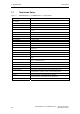
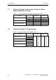
7.3 Tightening Torque, Cable cross sections for Power
Supply and Motor Terminals
Table 7-4 Power Supply & Motor Terminal Wire Sizes/Tightening Torques
Terminals
Units of
measurement
Case Size B Case Size C
[Nm] 1,3 1,3
Terminal Tightening Torque
[lbf.in] 12 12
[mm
2
] 1,5 2,5
Minimum Cable Cross Section
[AWG] 16 14
[mm
2
] 4 4
Maximum Cable Cross Section
[AWG] 12 12
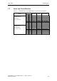
7.4 Tightening Torque for Fixing Screws
Table 7-5 Fixing Screw Recommended Tightening Torque
Description
Units of
measurement
Case Size B Case Size C
[Nm] 2,5 (M5) 2,5 (M5)
Inverter Cover Screws
[lbf.in] 21,3 (M5) 21,3 (M5)
[Nm] 0,8 (M3) 0,8 (M3)
Filter Board Retention Screws
[lbf.in] 7,0 (M3) 7,0 (M3)
[Nm] 0,8 (M3) 0,8 (M3)
I/O Board Retention Screws
[lbf.in] 7,0 (M3) 7,0 (M3)
[Nm] 1,5/2,5 M4/M5 2,5 (M5)
Terminal Housing to Motor Fixing
Screws
[lbf.in] 10,6/21,3 M4/M5 21,3 (M5)