
DVD Player User Manual

Issue 07/04 3 Functions
MICROMASTER 420 Operating Instructions
6SE6400-5AA00-0BP0
45
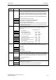
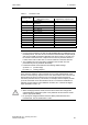
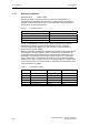
Table 3-3 Parameter P1000
Significance
Parameter values
Main setpoint source Supplementary setpoint source
0
No main setpoint -
1
MOP setpoint (motorized
potentiometer)
-
2
Analog setpoint -
3
Fixed frequency -
4
USS on BOP link -
5
USS on COM link -
6
CB on COM link -
10
No main setpoint MOP setpoint
11
MOP setpoint MOP setpoint
12 Analog setpoint MOP setpoint
..
.. ..
..
.. ..
66
CB on COM link CB on COM link
NOTE
Communications between the AOP and MICROMASTER are established using
the USS protocol. The AOP can be connected to both the BOP link (RS 232) as
well as at the COM link interface (RS 485) of the drive inverter. If the AOP is to
be used as command source or setpoint source then for parameter P0700 or
P1000, either "USS on BOP link" or "USS on COM link" should be selected.
The complete list of all of the setting possibilities can be taken from the
parameter list (refer to parameter list P1000).
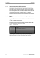
Parameters P0700 and P1000 have the following default settings:
a) P0700 = 2 (terminal strip)
b) P1000 = 2 (analog setpoint)
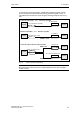
In this case, the selection of the command source is made independently of the
selection of the frequency setpoint source. This means that the source to enter the
setpoint does not have to match the source to enter the power-on/power-off
command (command source). This means, for example, that the setpoint (P1000 =
4) can be connected via an external device which is connected to the BOP link
interface via USS and the control ON/OFF command, etc. is entered via digital
inputs (terminals, P0700 = 2).
CAUTION
When modifying P0700 or P1000, then the drive inverter also changes the
subordinate BICO parameters (refer to the parameter list for P0700 or P1000
and the appropriate tables)
No priority has assigned between the direct BICO parameterization and
P0700/P1000. The last modification is valid.