
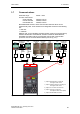
DVD Player User Manual

3 Functions Issue 07/04
MICROMASTER 420 Operating Instructions
94 6SE6400-5AA00-0BP0
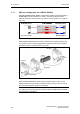
3.6.4 Analog output (DAC)
Number: 1
Parameter range: r0770 – P0781
Function chart number: FP2300
Features:
- cycle time: 4 ms
- resolution: 10 bit
- accuracy: 1 % referred to 20 mA
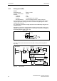
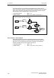
Setpoints, actual values and control signals inside the drive inverter are read-out
via the D/A converter using these analog input. The digital signal is converted into
an analog signal. All of the signals can be output via the D/A which contain the
"CO" abbreviation in the parameter text (refer to list of all of the BICO parameters
in the parameter list). Parameter P0771 defines, by assigning the parameter
number, the quantity which is output as analog signal through the DAC channel
(refer to Fig. 3-27). The smoothed output frequency is output, e.g. via the analog
output, if P0771 = 21.
D/A conv.
channel
D
A
KL
KL
D/A conv.−
D/A conv.+
r0755
Pxxxx
rxxxx
P0771
...
Function
r0020 CO: Freq. setpoint before RFG
r0021 CO: Act. filtered frequency
r0024 CO: Act. filtered output freq.
r0025 CO: Act. filtered output voltage
r0026 CO: Act. filtered DC-link volt.
r0027 CO: Act. filtered output current
r0052 CO/BO: Act. status word 1
r0053 CO/BO: Act. status word 2
r0054 CO/BO: Act. control word 1
...
0 ... 20 mA
Fig. 3-27 Signal output through the DAC channel
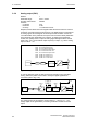
In order to adapt the signal, the DAC channel has several function units (filter,
scaling, dead zone) which can be used to modify the digital signal before
conversion (refer to Fig. 3-28).
DAC
scaling
P0777
P0778
P0779
P0780
DAC
dead zone
r0774
Function
P0781P0773
D
A
KL
KL
DAC
−
DAC+
r0755 Pxxxxrxxxx P0771
0 ... 20 mA
Fig. 3-28 DAC channel
NOTE
The analog output only provides the current output (0 ... 20 mA). A 0 ... 10 V
voltage signal can be generated by connecting a 500 Ohm resistor across the
output.