s 4 ACVATIX™ Control device PN25, safety function to DIN EN 14597 Preassembled valve-actuator combinations 387 MKB533.. MKB563.. MKC533.. MKC563.. MKD533.. MKD563.. · MK..533.. Operating voltage AC 230 V, 3-position control signal · MK..563.. Operating voltage AC 24 V, control signal DC 0...10 V, 4...20 mA or 0...1000 Ω · MK..563..
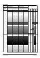
Type summary Control device MKB533.., MKD533.., MKB533..K, MKC533..K MKB563.., MKD563.. MKB563..K, MKC563..K Operating voltage AC 230 V AC 24 V Positioning signal 3-position DC 0…10 V, DC 4…20 mA, 0…1000 Ω Product number Stock number Product number 2-port valve Stock number Dpmax Dps [kPa] [kPa] DN kvs Sv [m3 / h] MKB533.15-0.5 S55329-M142-A110 MKB563.15-0.5 S55329-M142-A111 0,5 MKB533.15-0.63 S55329-M143-A110 MKB563.15-0.63 S55329-M143-A111 0,63 MKB533.15-0.
MKD533.25-5 S55329-M154-A100 MKD563.25-5 S55329-M154-A101 MKD533.25-6.3 S55329-M155-A100 MKD563.25-6.3 S55329-M155-A101 MKD533.25-8 S55329-M156-A100 MKD563.25-8 S55329-M156-A101 MKD533.25-10 S55329-M157-A100 MKD563.25-10 S55329-M157-A101 5 2100 6,3 25 8 10 1100 1200 32 MKD533.32-16 S55329-M159-A100 MKD563.32-16 S55329-M159-A101 MKD533.40-12.5 S55329-M160-A100 MKD563.40-12.5 S55329-M160-A101 MKD533.40-16 S55329-M161-A100 MKD563.40-16 S55329-M161-A101 MKD533.
Technical design The functional principle and technical details are described in valve and actuator data sheets: Product Electrohydraulic actuators Electrohydraulic actuators Electrohydraulic actuators 2-port valves Type SKB.. SKC.. SKD.. VVF53.. Data sheet N4564 N4566 N4561 N4405 Spring return facility The return spring causes the actuator to move to the «0%» stroke position and closes the valve. MK..533..
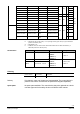
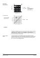
Positioning signal Y Position feedback U ON 12 DC 0…10 V 12 log = equal-percentage V100 Factory setting: All switches OFF control signal Y and volumetric flow Stroke calibration MK..563.. l in Relationship between l og 4567Z06 12 lin = linear ON ON OFF *) *) DC 4…20 mA 4567Z07 12 ON 4567Z05 ON Flow characteristic 4567Z08 DIL switches MK..563..
Override control input Z MK..563..
Accessories MK..533.. MK..563.. ASC9.3 ASZ7.3 double auxiliary switch potentiometer adjustable switching points ASZ7.3: 0…1000 Ω ASC1.6 auxiliary switch Switching point 0...
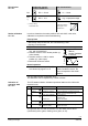
Technical and mechanical design The illustrations below show the basic design of the valves. Constructional features, such as the shape of plugs, may differ. 2-port valves DN 15…40 Fluids DN 15…40 Steam Closing against the pressure Closing with the pressure - 2-port valves pressure compensated - The VVF53..K valves use a pressure-compensated plug. This enables the same type of actuators to be used for the control of volumetric flow at higher differential pressures.
Sizing 30 15 20 3 4 5 6 8 10 1,5 2 0,3 0,4 0,5 0,6 0,8 1 0,2 0,03 0,04 0,05 0,06 0,08 0,1 0,02 0,01 Flow diagram 3000 800 2000 1500 600 500 400 300 250 200 150 1000 800 600 500 400 300 100 80 k VS 200 150 60 50 40 30 25 20 15 315 220 100 80 60 50 40 30 150 100 10 8 6 5 4 3 2,5 2 1,5 63 20 40 25 10 8 6 5 4 3 2 1 0,8 0,6 0,5 0,4 0,3 0,2 0,1 0,08 0,06 0,05 0,04 0,03 20 16 5 12. 10 8 6.3 5 4 3.2 2.5 2 1.6 5 1. 2 1 0.8 3 0.6 0.5 0.4 2 0. 3 5 0.2 0.2 6 0.
Valve flow characteristic Flow kv / kvs 1 0,8 0…30% ® linear 30…100% ® equal percentage ngl = 3 as per VDI / VDE 2173 0,6 0,4 0,2 0 0 0,2 0,4 0,6 0,8 1 Stroke H / H100 VVF53.125-220K VVF53.150-315 Flow rate kv / kvs For product lines: 0…100%: Linear Cavitation Cavitation accelerates wear on the valve plug and seat, and also results in undesirable noise.
25 2000 20 0 16 °C 15 °C 0 C 14 0 ° C 12 0 ° °C 10 80 1000 10 500 5 0 0 0 100 200 300 400 500 600 700 800 900 1000 1100 1200 1300 4382D05 P1 [kPa] 1 1500 Dpmax [kPa] Dpmax = Differential pressure with valve almost closed, at which cavitation can largely be avoided High temperature hot water example: p1 = Static pressure at inlet p3 = Static pressure at outlet M = Pump J = Water temperature Pressure p1 at valve inlet: Water temperature: p1 p3 M 4382Z06 J 0°C 8 P1 [bar] 2500
Working pressure [bar] Working pressure and medium temperature Fluids 25 24 23 22 21 20 19 18 1 0 0 1 20 80 100 120 140 160 180 200 220 240 Medium temperature [°C] Saturated steam Superheated steam Abs. operating pressure [bar] Working pressure and medium temperature staged as per ISO 7005 Current local legislation must be observed.
Engineering notes We recommend installation in the return pipe, as the temperatures in this pipe are lower for applications in heating systems, which in turn, extends the stem sealing gland's life. In open circuits the valve plug may seize as the result of scale deposits. We recommend that the valve should be exercised at regular intervals (two to three times per week). A strainer MUST be fitted at the valve inlet Ensure cavitation free flow (refer to page 10).
Orientation Direction of flow 90° 90° When mounting, pay attention to the valve's flow direction symbol ®. MK..5.. ® Direction of action: closes against pressure for DN15-40 Direction of action: closes against pressure for DN50-150 Commissioning notes The manual adjuster must remain secured with anti-tamper screws as factory delivered. When removing anti-tamper screws approval for the safety function to DIN EN 14597 ceases.
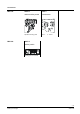
Automatic operation MKB../MKC.. The control device can only be operated in automatic mode. The crank (2) is snapped und sealed in the manual adjustment knob (1). When removing anti-tamper screws (3) approval for the safety function to DIN EN 14597 ceases MKD.. The control device can only be operated in automatic mode, i.e. the red indicator marked «MAN» is not visible. When removing anti-tamper screws (1) approval for the safety function to DIN EN 14597 ceases.
Maintenance notes The MK..5.. control devices are equipped with maintenance-free gland materials. When servicing the control device: · Never disassemble valve and actuator for maintenance or servicing else approval for the safety function to DIN EN 14597 ceases.
Warranty The technical data relating to specific applications are valid only in conjunction with the control devices listed in this data sheet under «Type summary», page 2. Approval as actuating device with safety function as per DIN EN 14597 applies to the entire actuator. Approval as actuating device with safety function as per DIN EN 14597 expires if the actuator is separated from the valve. This also voids any guarantees on the part of Siemens Switzerland Ltd. Technical data MKB533..
MKB533.. Signal inputs Terminal Y Signal inputs Override Control Z Signal outputs Position feedback U MKC533.. MKD533.. Voltage Input impedance Current Input impedance Signal resolution Hysteresis Resistor Z not connected Z connected directly to G Z connected directly to G0 Z connected to M via 0...
MKB533.. Zubehöre ASC1.6 Hilfsschalter Switching capacity ASC9.3 Hilfsschalterpaar ASZ7.3 Potentiometer Switching capacity per auxiliary switch Change in overall resistance of potentiometer 1) MKC533.. MKD533.. MKB563.. MKC563.. MKD563.. AC 24 V, 10 mA...4 A ohm., 2 A ind. AC 250 V, 6 A ohm., 2.5 A ind. 0…1000 W The documents can be downloaded from http://siemens.com/bt/download.
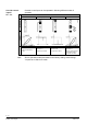
Internal diagrams MKB533.., MKC533.., AC 230 V, 3-position c 0% 0% solenoid valve for spring-return a, b, c ASZ7.. potentiometer c 0% end switch n c1, c2 ASC9.3 double auxiliary switch Cm1 MKD533.. AC 230 V, 3-position Cm1 0% Y1 Positioning signal «open» Y2 Positioning signal «close» 21 spring-return function N neutral conductor Cm1 end switch n solenoid valve for spring-return c1, c2 ASC9.3 double auxiliary switch a, b, c ASZ7.. potentiometer Cm1 MK..563..
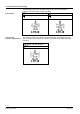
Connection diagrams MKB533.., MKC533.., 3-position F1 AC 230 V max. 6 A (L) F1 (Y1) (Y2) (N) N1 0% N1, N2 Y1, Y2 safety limiter (e. g. temperature limiter) controller actuators L N Phase neutral (Y1) (Y2) Y1 Y2 controller contacts controller contacts Positioning signal «open» Positioning signal «close» 21 spring-return function F1 N1, N2 Y1, Y2 safety limiter (e. g.
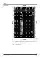
Dimensions All dimensions in mm MKB.., MKC.. MKD.. B B A AB B ► = > 100 mm Minimum clearance from ceiling or wall for mounting, connection, operation, maintenance etc. ►► = > 200 mm DN B D D2 D1 K Ø Ø Ø Ø 46 65 130 65 87.5 95 L1 L2 L3 kg H MKB.. MKC.. MKD.. MKB.. MKC.. 15 14 20 16 105 14 (4x) 56 75 150 75 99.5 25 15 115 65 85 160 80 104.
Revision numbers for control devices MK..5.. Type Valid from Rev.-No. MKB533..K MKB563..K MKC533..K MKC563..K MKB533.. MKB563.. MKD533.. MKD563.. Actuator, refer to data sheet N4564: SKB Actuator, refer to data sheet N4566: SKC Valve, refer to data sheet N4405: VVF53..
Published by: Siemens Schweiz Ltd. Building Technologies Division International Headquarters Theilerstrasse 1a 6300 Zug Schweiz Tel. +41 58-724 24 24 www.siemens.com/buildingtechnologies © Siemens Schweiz Ltd.