
Data Sheet for Product


10 / 24
Siemens Control device PN25, safety function to DIN EN 14597 CE1N4387en
Building Technologies 2020-04-29
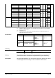
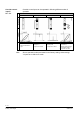
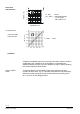
Flow k
v
/ k
vs
0,8
0,6
0,4
0,2
0
1
0 0,2 0,4 0,6
0,8
1
0…30% ® linear
30…100% ® equal percentage
n
gl
= 3 as per
VDI / VDE 2173
Stroke H / H
100
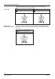
Flow rate k
v
/ k
vs
0…100%: Linear
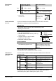
Cavitation accelerates wear on the valve plug and seat, and also results in
undesirable noise. Cavitation can be avoided by not exceeding the
differential pressure shown in the flow diagram on page 9 and by adhering
to the static pressures shown below.
To avoid cavitation in chilled water circuits ensure sufficient counter
pressure at valve outlet, e.g. by a throttling valve after the heat exchanger.
Select the pressure drop across the valve at maximum according to the
80 °C curve in the flow diagram below.
Valve flow
characte
r
istic
For product lines:
VVF53.125-220K
VVF53.150-315
Cavitation
Note on chilled
water