
User Manual

Functional capabilities
20
Building Technologies 053_DMS_MM8000_MP4.15_System_Description_A6V10062417_a_en
Fire Safety & Security Products 06.2008
suspend the fault, and then return to assisted treatment of the first event with
minimal loss of time.
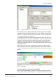
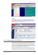
2.1.5 Plant browser
The MM8000 Plant browser is the tool for navigating through the various levels of
your facility. It provides comprehensive information about the subsystem hierarchy
of all the available sites. The MM8000 Plant browser allows you to view detailed in-
formation about your security management system.
The Plant browser allows you to manage all the MM8000 points configured in the
installation, and to navigate through the pages of the plant. Its main purpose is to
dynamically report the state of the MM8000 points, and let you issue any neces-
sary commands. The data points can display additional information such as proper-
ties and states.
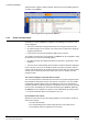
The following are some common types of tasks you would perform using the
MM8000 Plant browser:
− Checking the status of an area
− Show live CCTV images of an area
− Unlock a door
− Turning a section off or on (exclude or include)
− Disconnecting a detector (or group of detectors) to prevent false alarms from
being generated
− Putting a section into ‘Test’ mode
− Switching a detector, zone, or area off-duty and on-duty
− Switching an area between day and night modes
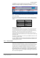
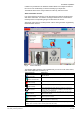
What you see when using the Plant browser
The information displayed on the left side of the monitor is organised similarly to
that found in Windows Explorer. While the organisation of each plant varies from
company to company, different folders in the “Explorer”-type window or “hierarchi-
cal tree” usually represent the main areas of the plant. For example, if your plant
has multiple buildings, a separate folder may represent each building. In each
folder, you should find the control units that monitor that area.
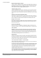
Geographical, Logical, and Physical trees
The Plant Browser allows for multiple views of the safety and security subsystems
and devices managed by MM8000. Three types of inter-related views are sup-
ported:
• Geographical View: shows the geographical layout of the detectors in the facility
by building, floor, section, and room. This view is geared toward operators who
need intuitive and simple access to the safety and security devices;
• Logical View: shows how detectors are conceptually grouped, using levels such
as areas, sections, and zones, as they are used in the local safety and security
subsystems;
• Physical View: shows the hardware units, lines, and devices for technical pur-
poses; the physical view represents the system structure for technical mainte-
nance operations.
Each operator group profile can be associated to one of these views. When they
open the plant browser, the associated view will be their preferred (default) view-
Also, customized filter can be setup and saved individually by the operators in or-
der to always provide the preferred view on the plant.