Read/Write Devices MOBY I Configuration, Installation and Service Manual (4) J31069-D0033-U001-A8-7618 5 5-1
Read/Write Devices 5.1 Introduction Application area The read/write devices (i.e., SLGs) provide inductive communication with the mobile data memories (i.e., MDSs) and the serial link to the interfaces (i.e., ASMs). Various SLG models – for short, medium and long distances to the MDS – are available to meet customer requirements. Layout and functions The SLG executes commands received from the interface. These commands for reading and writing data are converted via a modulator/demodulator circuit.
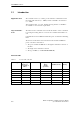
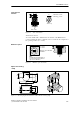
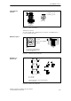
Read/Write Devices 5.2 SLG 40 Application area The SLG 40 is extremely suited for use on small assembly lines. The short installation distance between several SLG 40 antennas is a special feature. With the 2 included screw nuts, the antenna head can be positioned with extreme precision for each application. Figure 5-1 Read/write device SLG 40 Ordering data Table 5-2 Ordering data for SLG 40 Read/write device SLG 40 up to 10 mm (low power), incl.
Read/Write Devices Table 5-3 Technical data of SLG 40 Housing Dimensions (in mm) For antenna head (∅ x threading x L) For electronics w/o plug (WxHxD) Color Antenna SLG housing Material Antenna SLG housing Plug connection Protection rating Antenna and SLG housing Shock Vibration Mounting of SLG Turning moment (at room temperature) Ambient temperature During operation During transportation and storage Weight (approx.
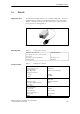
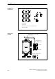
Read/Write Devices Transmission window Ld Ld sg Field at Sa = 2 mm sa Field at Sa = 8 mm View of top View of side Figure 5-2 View of the antenna Transmission window: To ensure reliable data communication, the antenna of the MDS must be positioned within this field. A diameter of Ld = 18 mm can be configured for the operating distance (2 to 8 mm).
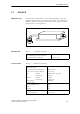
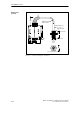
Read/Write Devices Definition of distance D Da Db Da Db 50 mm 80 mm The SLG electronics can be mounted directly next to each other. Figure 5-5 Distance D for SLG 40 Dimensions (in mm) Anti-kink cable protector, flexible in all directions Minimum bending radius: 20 mm 40 5.5 Cable length 0.
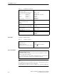
Read/Write Devices 5.3 SLG 40-S Application area The SLG 40 is extremely suited to use in small assembly lines. The short installation distance between several SLG 40-S antennas is a special feature. With the 2 included screw nuts, the antenna head can be positioned with extreme precision for each application. Figure 5-7 Ordering data Technical data Table 5-5 Read/write device SLG 40-S Ordering data for SLG 40-S Read/write device SLG 40-S up to 8 mm (low power), incl.
Read/Write Devices Table 5-6 Technical data of SLG 40-S Operating voltage Current consumption Field data 17 to 30 V DC Idle 25 mA Operation 90 mA Serial interface Transmission speed Max. cable length (cf. chap. 3.10.1; standard cable) MTBF Transmission frequency RS 422 19200 baud 360 m S Power S Data 134 kHz Mounting of SLG 4 M5 screws Turning moment (at room temperature) Mounting of SLG head (included) 2 Nm 2 nuts (M18 x 1.0) Weight (approx.
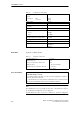
Read/Write Devices Transmission window Ld Ld sg Field at Sa = 2 mm sa Field at Sa = 8 mm View of top View of side Figure 5-8 View of the antenna Transmission window: To ensure reliable data communication, the antenna of the MDS must be positioned within this field. Metal-free space a a = 10 mm b = 10 mm a b MOBY I SLG 40-S Metal-free space with flush installation Note: The limit and operating distances are reduced when the metal-free space is not adhered to.
Read/Write Devices Dimensions (in mm) Anti-kink cable protector, flexible in all directions 50 Minimum bending radius: 20 mm Cable length 0.5 m Antenna head 75 65 Screw nuts 30 25 5 M18 Fine threading Pitch 1.0 5 18 5.