Table of Contents MOBY I Configuration, Installation and Service Manual 6GT2 097-4BA00-0EA2 Published in January, 2002 General 1 Introduction to MOBY I 2 Configuration and Mounting Guidelines 3 Mobile Data Memories 4 Read/Write Devices 5 Interfaces 6 Accessories 7 Documentation A Error Messages B ASCII Table C Compatibility D
Safety Guidelines ! ! ! This manual contains notices which you should observe to ensure your own personal safety, as well as to protect the product and connected equipment. These notices are highlighted in the manual by a warning triangle and are marked as follows according to the level of danger. Danger indicates that death, severe personal injury or substantial property damage will result if proper precautions are not taken.
Configuration and Mounting Guidelines MOBY I Configuration, Installation and Service Manual (4) J31069-D0033-U001-A7.
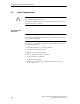
Configuration and Mounting Guidelines 3.1 Basic Requirements ! Warning Do not make changes to the devices. Violation will invalidate interference emission certification (BZT, FCC), CE and the manufacturer’s warranty. FCC Compliance Statement Note Any unauthorized modifications to this device could void the user’s authority to operate the equipment. To choose the correct MOBY I components, apply the following criteria to your particular application. Transmission distance (i.e.
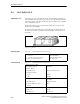
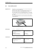
Read/Write Devices 5.4 SLG 41/SLG 41-S Application area The SLG 41 is a low-end read/write device. It is particularly suitable for use when the MDS conveyor system (e.g., pallets) can be physically positioned relatively precisely. The swivel head of the SLG 41 makes it very adaptable to the transportation system. In dynamic operation, only a small amount of data can be read or written between SLG 41 and MDS.
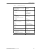
Read/Write Devices Table 5-9 Technical data of SLG 41/SLG 41-S Current consumption Idle/operation 20 mA / 90 mA MTBF 2 x 10⁶ Housing Dimensions in mm (W x H x D) 120 x 40 x 40 Color Anthracite/ergo-gray Material Polyamide 12 Plug connection DIN 43651 Protection rating IP65 Shock 50 g Vibration 20 g Mounting of SLG 4 M5 screws Turning moment (at room temperature) 3 Nm Ambient temperature Field data During operation –25° to +70° C During transportation and storage –40° to +85° C
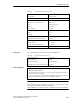
Read/Write Devices Transmission window Transmission window at operating distance M SLG 41-S M M Transmission window at operating distance Figure 5-13 SIEMENS M Length of transmission window (L) Metal-free space ÏÏÏ ÏÏÏ ÏÏÏ ÏÏÏ ÏÏÏÏÏÏ ÏÏÏ ÏÏÏ ÏÏÏ ÏÏÏ ÏÏÏ ÏÏÏ SIEMENS Length of transmission window (L) Transmission window of SLG 41/SLG 41-S ÏÏÏÏÏÏÏÏÏÏÏ ÏÏÏÏÏÏÏÏÏÏÏ ÏÏÏÏÏÏÏÏÏÏÏ ÏÏÏÏÏÏÏÏÏÏÏ ÏÏÏÏÏÏÏÏÏÏÏ ÏÏÏÏÏÏÏÏÏÏÏ ÏÏÏÏÏÏÏÏÏÏÏ ÏÏÏÏÏÏÏÏÏÏÏ ÏÏÏÏÏÏÏÏÏÏÏ ÏÏÏÏÏÏÏÏÏÏÏ ÏÏÏÏÏÏÏÏÏÏÏ ÏÏÏÏÏÏÏÏÏÏÏ a a SIEMENS
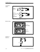
Read/Write Devices Dimensions (in mm) SLG 41: 40 28 80 SIEMENS 40 40 49 25 Position of swivel head on delivery 30 60 .3 5,3 40 14.5 SLG 41-S: 40 28 40 40 80 SIEMENS Possible read head changes with the swivel head 49 60 40 Position of swivel head on delivery 30 5.3 Figure 5-16 25 14.
Read/Write Devices 5.5 SLG 41C/SLG 41CC Application area The SLG 41C is a low-end read/write device. It is small and compact and is excellent for use in small assembly lines. The high protection rating and use of high-quality materials ensure that the SLG 41C can easily handle even most rugged industrial conditions. It is connected with a 3-m cable which is equipped with core sleeves at the end. This connection line can be extended with terminals or a user-provided connection plug.
Read/Write Devices Table 5-12 Technical data of SLG 41C/41CC Serial interface to evaluation unit RS 422 Data transmission rate 19 200 Baud Line length, ASM-SLG max.
Read/Write Devices Field data (in mm) Table 5-13 Field data of SLG 41C/41CC MDS 401/402 MDS 403 MDS 404/514 Working distance (Sa) 0 to 6 4 to 15 0 to 12 Limit distance (Sg) 10 30 25 L: Vertical 2L: Horizontal 20 65 30 40 – 60 Width of transmission window (W) 8 25 12 Transmission window Minimum distance from SLG to SLG 200 200 200 FCC information Made in Germany SIEMENS MOBY I SLG 41C THIS DEVICE COMPLIES WITH PART 15 OF THE FCC RULES: OPERATION IS SUBJECT TO THE FOLLOWING T
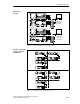
Read/Write Devices Transmission window 12 M Transmission window at working distance M 12 20 Length of the transmission window (L) for MDS 401/402 M 5 5 M 30 Length of the transmission window for (L) MDS 404/514 L = 65 Length of the transmission window SIEMENS M Transmission window at working distance B = 25 Width of the transmission window Lenght of the transmisison window for MDS 403 Figure 5-19 The transmission window is marked on the housing The MDS moves along the “SIEMENS” label on the h
Read/Write Devices Metal-free space a SIEMENS MOBY I SLG 41C a a a a = 15 mm Metal-free area with flush installation Figure 5-20 Metal-free area of SLG 41C/41CC Definition of distance D SIEMENS MOBY I SLG 41C Minimum distance from SLG to SLG D = ≥ 200 mm D D SIEMENS MOBY I SLG 41C Figure 5-21 5-20 SIEMENS MOBY I SLG 41C Distance D: SLG 41C/41CC MOBY I Configuration, Installation and Service Manual (4) J31069-D0033-U001-A7.
Read/Write Devices Dimensions (in mm) 30 55 75 ∅ 5.5 65 SIEMENS MOBY I SLG 41C 55 45 Core color Designation Brown – Receiving Pink + 24 V Gray Ground (0V) Green + Sending Yellow – Sending White + Receiving Black Cable shield 30 Core and sleeves Flexible cable anti-kink guard 0.1 m 3m 75 ∅ 5.5 65 SIEMENS MOBY I SLG 41CC 55 45 30 2m Figure 5-22 Dimensions of SLG 41C/41CC MOBY I Configuration, Installation and Service Manual (4) J31069-D0033-U001-A7.