
Installation Instructions


Siemens Building Technologies, Inc.
8 Fernwood Road • Florham Park, NJ 07932
Tel: (973) 593-2600 • Fax: (973) 593-6670
Web: www.faradayfirealarms.com
P/N 315-447345-4
PAGE 1 OF 4
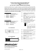
INSTALLATION INSTRUCTIONS AND WIRING FOR
CAT. NO. SLU-2 SERIAL ANNUNCIATOR UNIT
AND
CAT. NO. SLE-16 SERIAL ANNUNCIATOR EXTENDER
The SLU-2 Annunciator Unit is an optional accessory for the MPC-6000 and MPC-7000 Fire Alarm
System Control Unit. The SLU-2 includes a processor board and an annunciator driver board. The
processor board receives commands from the control unit for activating the outputs and transmits
supervision and control functions to the control unit. The processor board can control up to 4 annunciator
driver boards. Each driver board provides 16 outputs for LEDs or incandescent lamps. The control unit
can address up to 8 Serial Relay Units and/or Serial Annunciator Units. Auxiliary power supplies will be
required to power units beyond the control unit capability.
SLU-2 PARTS SUPPLIED
1 557-413829 Processor Board Assembly
1 557-413322 Annunciator Driver Board Assembly
1 555-446653 34 pin Cable Assembly, 3 1/2”
1 195-447042 PCB Track, 14 1/2”
3 555-447080 10 pin Cable Assembly, 6”
2 899-G67197 Keps Nut, #6-32
1 235-443269 Screwdriver
1 315-447345 Instruction Sheet
SLE-16 PARTS SUPPLIED
1 557-413322 Annunciator Driver Board Assembly
1 555-446652 34 pin Cable Assembly, 15”
1 555-446653 34 pin Cable Assembly, 3 1/2”
1 195-447042 PCB Track, 14 1/2”
2 555-447080 10 pin Cable Assembly, 6”
2 899-G67197 Keps Nut, #6-32
1 315-447345 Instruction Sheet
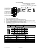
SLU-2 DIMENSIONS
SLE-16 DIMENSIONS
Step 1.) Installation is to be done by qualified personnel
who have thoroughly read and understood this
instruction sheet.
Step 2.) Disconnect BATTERY and AC prior to working on
equipment.
Step 3.) Mount enclosure that is UL Listed for Fire
Protective Signaling Use such as the FAE-21 Fire
Alarm Accessory Enclosure (P/N 500-
401403014FA), as required.
Step 4.) Attach conduit and run wires as required.
Step 5.) Set processor board dip switch (SW-1) for proper
remote address (See SLU-2 Address Setting).
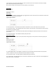
Step 6.) Set jumper P6 for desired buzzer operation.
P6 – BUZZER ACTIVATION
REMOTE
LOCAL (Processor Board Buzzer)
When “Local” is selected, the buzzer
follows the sounder on the panel. When
“Remote” is selected, the buzzer does
not activate but the “Remote Buzzer
Output” pin signal of P2 follows the
sounder on the panel.
Step 7.) Mount PCB Track(s) using #6-32 keps nuts (P/N
899-G67197) and snap in PCB assemblies.
Step 8.) Plug in the cable assembly(s) to the PCB
assemblies as required.
Step 9.) Connect IN wires from fire alarm system control
unit or previous remote as required.
Step 10.) Connect OUT wires to next remote or 120 ohm
E. O. L. Resistor Assembly (P/N 140-050008-1), if
last remote.
Step 11.) Connect LEDs or lamps, as required.
Step 12.) Apply power to system.
Step 13.) Program control unit for required annunciator
operation.
Step 14.) Check for proper operation of functions.